
Configure AcuView Software Settings
- From the left navigation panel click on the "Settings" settings, then select "General" to view and change different system settings such as meter password, wiring, Baud rate, parity, PT and CT ratios.
- Make sure you click "Update Device" after making changes, so that the changes can be saved on the meter.
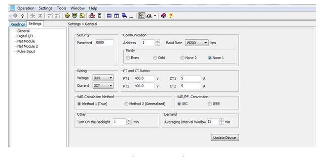
Figure 1: General Settings
Configure the Digital I/O Settings from AcuView
- From the left navigation panel click on the "Settings" tab then select "Digital I/O" to set up the two Digital Outputs and 4 Digital Inputs. This is only available on the Acuvim DL and EL meters.
Note: Make sure you click "Update Device" after making changes, so that the changes can be saved on the meter.
There are two Digital Outputs:
- You can set up the digital output either as an energy pulse output or an alarm output.
DO1 Type or DO2 Type:
- Select the DO type based on what you want, i.e. either "Energy Pulse" or "Alarm"
Choose the DO Energy Pulse Mode:
- If any or both of the digital outputs are set as energy pulse select what type of energy you want DO1 or DO2 to output. E.g. Ep_imp, Ep_exp etc.
You can then set the Pulse width and the Pulse constant. Here is the procedure for calculating the pulse constant (based on your meters firmware)
Procedure for meters with firmware 2.01 or newer
First you need to figure out how many pulses you need to represent 1 KWh or how many KWh will represent 1 pulse. The former is focused on smaller consumption.
In this procedure, we will assume 1 pulse = 10kWh is what is needed. Then follow these steps:
- Multiply the PT ratio and CT ratio i.e. PT1/PT2 * CT1/CT2 Example: PT ratio: 6600V/120V, CT ratio: 2000:5A => 6600/120 * 2000/5 = 22,000 NOTE: If no PTs were used, enter the PT ratio as the default on the meter, i.e. 400/400. If the CT2: 333mV, consider this as 1A for the calculation
- Divide 10KWh by 22,000 i.e. (10/22000) kWh = (1/2200) kWh
- This means 1 pulse = (1/2200) kWh; therefore 2200 pulses = 1 kWh
- Since we get 1 kWh = 2200 pulses, enter 2200 into the software
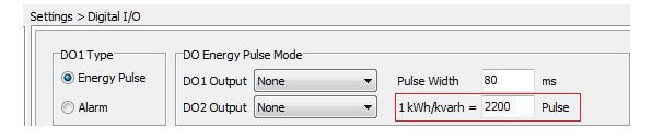
Figure 2: Setting the Digital Output Pulse Constant
Procedure for meters with firmware older than 2.01
First you need to figure out how many pulses you need to represent 1 KWh or how many KWh will represent 1 pulse. The former is focused on smaller consumption.
You will need to enter the pulse constant based on the unit. The unit of the pulse constant is 0.1kWh (or kvarh).
If you want 1 pulse to represent 100kWh, this is equivalent to 1 pulse = 1000*0.1kWh. Therefore 1000 is the number you will enter into the software.
Set the DO Alarm Limit:
- You can set the DO Alarm Channel, Setting, Setpoint and Delay (ms) in this section.
Configure the Alarm Backlight:
- You can enable or disable backlight flashing during an alarm, by turn on or off the alarm backlight.
Configure the Module Communication:
- You can set the Baud Rate and Parity for the second RS-485 module.
Set the Digital Inputs:
- You can set the DI type, for all 4, either as "State" or "Counter".
If DI type is "State", it means the DI will act as a switch status monitor.
If DI type is "Counter", it means DI will act as a pulse counter.
- In this case, type in the pulse constant in the "DI Pulse Const" section. When the number of pulses counted by the DI equals to the pulse constant, the pulse counter number will increase by one.
Configure Pulse Input Settings
When the Digital Input (DI) is set as a pulse counter, you can set up what each count on the meter will represent.
- You will have to set the DI Type as Counter and also set the DI pulse constant from the "Digital I/O" settings section.
Example: Set DI 1 Type as a counter, and let's make 5 pulses = 1 (count). This means after 5 pulses, the meter count will increase by 1.
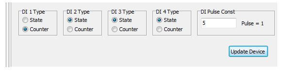
Figure 3: Setting Digital Input Type
Under the "Pulse Input" Settings:
- You can set what the count represents. In this example, we set DI1 count to represent 20kWh.

Figure 4: Pulse Input Settings
Therefore: 5 pulses = 1 count = 20kWh.
- Make sure you click "Apply" at the button of the screen once all changes have been made.
You can click on "Advanced Options" to add new categories and/or units.
Note: After the settings have been done, you can read the information by clicking on "Readings" tab, "Energy", "Real-Time". It is located under the "Pulse Input" section.
Configure Time-of-Use Settings for the Acuvim EL
From the left navigation panel located click on the "Settings" tab and select "TOU" in the settings tab to set up the Time of Use (TOU) function.
Here is an example to help illustrate how to set up TOU:
Time of Use Rate (Example):
Winter Rate (November 1 – April 30):
- On-peak: 7am-11am and 5pm-7pm weekdays
- Mid-peak: 11am-5pm weekdays
- Off-peak: 7pm-7am and all day weekends/statutory holidays
Summer Rate (May 1 – October 31):
- On-peak: 11am-5pm weekdays
- Mid-peak: 7am-11am and 5pm-7pm weekdays
- Off-peak: 7pm-7am and all day weekends/statutory holidays
There are 10 holidays in the year based on the example: Jan 1, Feb 17, April 18, May 19, July 1, Aug 4, Sept 1, Oct 13, Dec 25 and Dec 26.
Here is how you set the TOU settings based on the above rate.
Under the "General" Section:
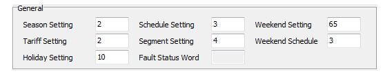
Figure 5: Time-of-Use Settings
Season Setting: 2 (Since there are two different seasons in the year: winter and summer)
Schedule Setting: 3 (2 different Weekday schedule and a weekend/holiday Schedule)
Segment Setting: 4 (7am to 11am, 11am to 5pm, 5pm to 7pm and 7pm to 7am)
Tariff Setting: 2 (On-peak, Mid-Peak and Off-Peak)
- There are four tariffs available in the Acuvim EL. They are sharp, peak, valley and normal each represented by 0-3 respectively. In this example, we have 3 tariffs so we enter 2 in the settings; this will mean sharp, peak and valley will be used. We can represent sharp (0) as mid-peak, peak (1) as On-peak and valley (2) as Off-peak in our example.
Weekend Setting: Type in 65 to enable Saturday and Sunday as the weekend. This is calculated based on the following:
| Days | Sunday | Monday | Tuesday | Wednesday | Thursday | Friday | Saturday |
|---|---|---|---|---|---|---|---|
| Enable | 1 | 0 | 0 | 0 | 0 | 0 | 1 |
Note: 1 to enable, 0 to disable.
Therefore: Convert 1000001 from binary to decimal = 65
Weekend Schedule: 3 (This means Schedule 3 will be used for weekends/holidays)
Holiday Setting: 10 (This is the number of holidays in the year).
Fault Status Word: If there is an error as a result of the settings, a number will be displayed in this box e.g. Fault Status Word 0140 ; if there is no error, the section will show as Fault Status Word 0000
Under the "Monthly Billing Mode" Section: Choose the monthly billing mode either as "End of Month" or "Assign" a certain time.
Also make sure to check the "Enable TOU" box.
Under the "Daylight Saving Time" Section: You can enable daylight saving. Select the required format:
- Format 1 is used to set the daylight savings period at a fixed date and time. I.e. March 8, 2015 at 2am
- Format 2 is used to set the daylight savings period at a non-fixed date I.e. 2nd Sunday in March at 2am.
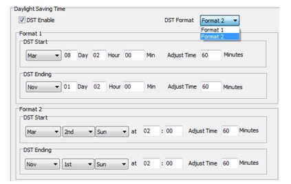
Figure 6: Daylight Savings Time Configuration
For TOU Seasons format MM-DD ID: MM stands for month, DD for day and ID for TOU Schedule number being used for that season. The date should be in sequence according to the calendar year, that is, the earlier date should come first and later date comes last.
Holidays format MM-DD ID: MM stands for month, DD for day and ID for the TOU schedule number being used for holidays.
TOU Schedule #1-#14 format HH:MM ID: HH stands for hour (24 hour format), MM for minutes and ID for the tariff number used. The time should be organized according to the hour sequence.
Based on the example, here is a screenshot of how the TOU Seasons, Holidays, TOU Schedule # sections should be filled.
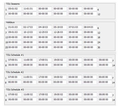
Figure 7: TOU Schedule Settings
After the TOU settings have been completed, make sure to click “Update Device”. If the settings were done right, the TOU settings will take effect; if not, an error message will be displayed.
Note: If there is an error, a number will be displayed in the "Fault Status Word" box e.g. Fault Status Word 0140; if there is no error, the section will show as Fault Status Word 0000
TOU Holiday Settings
Typically the holidays are not on fixed dates every year. As a result of this, you can use the "TOU Holiday" setting to set up holidays for up to 10 years. This is only available on the Acuvim EL.
Make sure you "Enable Holidays Years Settings".
Put in the "Start Year" and "Ending Year" for your 10 year (or less) range. E.g. 2014 – 2023.
Fill in the holiday information for each year. Holidays format MM-DD ID: MM stands for month, DD for day and ID for the TOU schedule number being used for holidays.
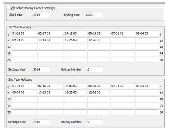
Figure 8: TOU Holiday Settings
After all the information has been filled out, make sure you click "Update Device"
Set Data Log
This applies to all Acuvim L Meters except AL and BL.
Acuvim L series meters do not have onboard memory for data logging, but you can log data on your computer's memory.
You must always be connected to the software for this data log method to work
You can access the data log setting by clicking on the "Settings" option located on the menu toolbar, and then clicking on "Data Log Settings".
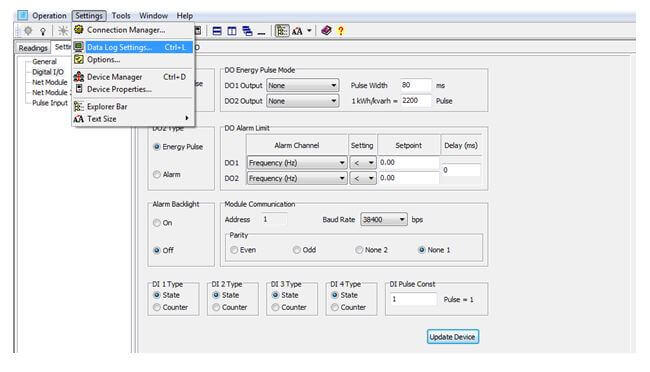
Figure 9: Accessing the Data Log Settings
The Data Log Setting window will open. This is shown below:
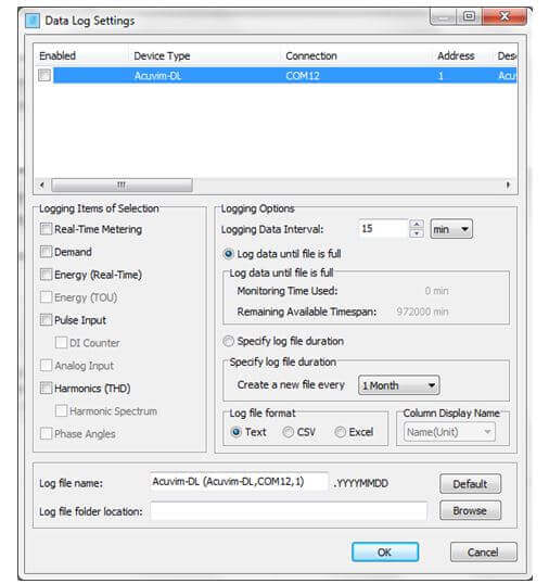
Figure 10: Data Log Settings
- Make sure you check the "Enabled" box in the window.
Under the "Logging Items of Selection" Section:
- Click on the required groups of parameters you will like to log.
Under the "Logging Options" Section:
- Choose the "Logging Data Interval".
- Choose between the options "Log data until file is full" or "Specify Log file duration"
If "Specify Log file duration" is selected:
- Choose how often you want a new file created.
- Choose the "Log file format" you want the file(s) saved as.
Give the file a name by typing in the preferred "Log file name" to save the file.
Choose the "Log file folder location" where the file(s) will be saved.
Once everything is set, click "OK".
Finally, make sure you click the icon:![]() on the top of the screen to start data logging on the computer.
on the top of the screen to start data logging on the computer.
You can click the icon:![]() on the top of the screen to stop data logging.
on the top of the screen to stop data logging.
WARNING:
If Excel is chosen as the Log file format, After you click on the icon: ![]() to start data logging, a warning window will pop up. Take note of the warning in order to prevent your files from being corrupt.
to start data logging, a warning window will pop up. Take note of the warning in order to prevent your files from being corrupt.
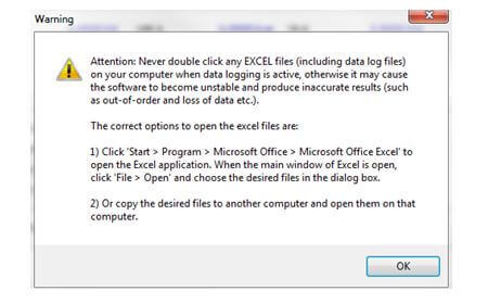
Figure 11: Warning Message