
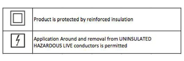
Key Symbols
What's Included with the AcuCT 5A
- 3.5 ft leads
- 3* screws and screw caps (Not included with the AcuCT 0812 Split Core CT Series)
Warning: Disconnect power supply before making electrical connections.
Warning: Current Transformers (CT’s) should be installed by trained electrician or technician.
Warning: The secondary circuit of a CT should not be opened when current is flowing through the primary circuit.
Installation Steps for AcuCT 5A
- Unscrew the thumb screws to remove the top portion of the CT and remove the screws so the CT can be split up into parts for installation.
- Install the CT around the conductor to be measured. Verify the CT is installed with the CT label reading 'P1' or 'S1' facing towards the wire direction of the source.
- Similarily verify that the CT is installed with the CT label reading 'P2' or 'S2' facing towards the wire direction of the load.
- Reattach the removable top portion of the CT and tighten the thumb screws.
- Mount CT using mounting clips ( For more information see Appendix).
- Connect leads to the CT terminals.
- Connect the CT lead that is connected on the 'S1' side of the CT to the 'I11' terminal on the Acuvim meter or the (+) terminal if using another meter.
- Connect the CT lead that is connected on the 'S2' side of the CT to the 'I12' terminal of the Acuvim meter or the (-) terminal if using another meter.
- Repeat Steps 1 through 4 if using more than one CT.
Mounting AcuCT 5A CTs on a Busbar or Cable
For mounting the CT on a busbar or cable, the following should be applied:
- Place the screw caps at the end of the screws
- Position the washer on the screw to the desired postion on the screw
- Insert washer into the small opening located near the window of the CT so that the screw cap is touching busbar/cable.
- Ensure that the screw caps are firmly securing the busbar and cable.
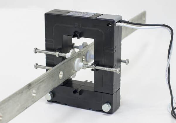
Figure 1: Mounting the AcuCT-5A to a Busbar
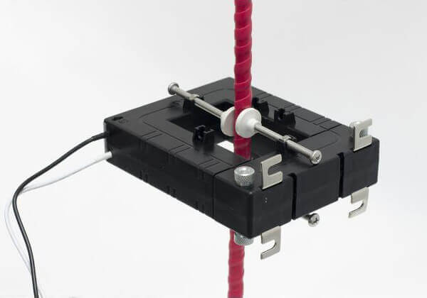
Figure 2: Mounting the AcuCT-5A to a Cable
Mounting AcuCT 5A CTs on a Wall or Flat Surface
For mounting the CT on a surface, the following should be applied:
- Place the mounting clips in the slots located by the removable top portion.
- Ensure mounting clips are securely placed in the slots.
- Using four screws (not included), place the screws through the mounting clips and tighten to attach to surface.
Caution:
This equipment is intended to be used as a current transformer. If the equipment is used in a manner not specified by the manufacturer, the protection provided by the equipment may be impaired.
Important: The secondary winding shall not be left open when the primary side of equipment is installed on live system. No cleaning is required.
Environmental:
The CT is rated for indoor use only. The altitude is up to 2000 meters Ambient Temperature range is -20°C to 40°C Maximum relative humidity is 85% for temperature up to 31°C decreasing linearly to 50% relative humidity at 40°C Rated pollution degree 2