
EV300 Install Guide
We walk through the installation of the EV300 power and energy meter in a number of configurations.
Voltage and Current Connection
Here are some of the common installation methods, their respective diagrams and meter configurations. For other installation methods not mentioned here, please consult the users manual.
Three Phase: 4 wire-connection (Three phase with a neutral)
With Direct Voltage Connection
Direct voltage connection is used if you have a system voltage lower than 230VLN or 400VLL. The connection diagram is shown below (Figure 1).
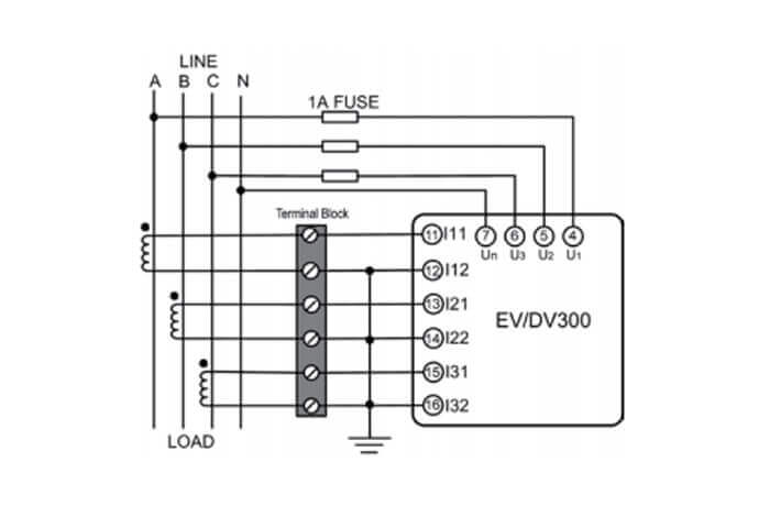
Figure 1: Meter Configuration: 3LN, 3CT
The following connection can be made if only 2 CT's are available.
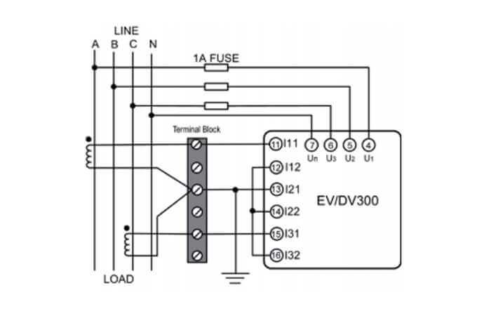
Figure 2: Meter Configuration: 3LN, 2CT
With Potential Transformers (PTs)
PTs are required if you have a system voltage higher than 230V LN or 400V LL. The connection diagram is the same as the direct voltage connection above (Figure 1), with the exception of the PT connections for the voltage lines. The PTs should be connected as shown below (Figure 3).
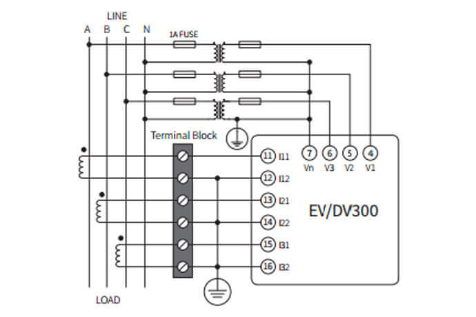
Figure 3: Meter configuration: 3LN, 3CT
Three Phase: 3 wire-connection (Three phase without a neutral)
This will be the same diagram as the three phase 4-wire direct voltage connection shown above (Figure 1), with the exception of a neutral connection. NOTE: Direct voltage connection is used if you have a system voltage lower than 400V LL (±20%)
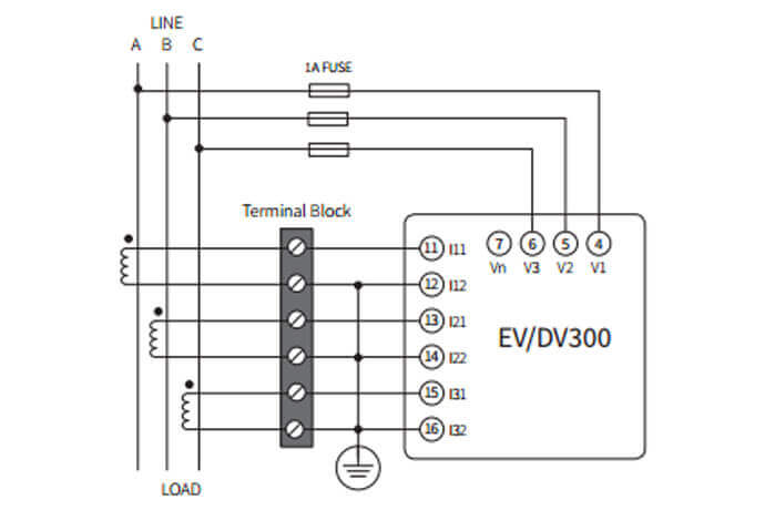
Figure 4: Meter Configuration: 3LL, 3CT
With Potential Transformers (PTs)
PTs are required if you have a system voltage higher than 400V LL. Instead of connecting the voltage lines directly to the meter as shown in Figure 4, the voltage lines are connected to the meter using PTs. The PTs should be connected as shown below (Figure 5).
Note: Two PTs are needed for this connection.
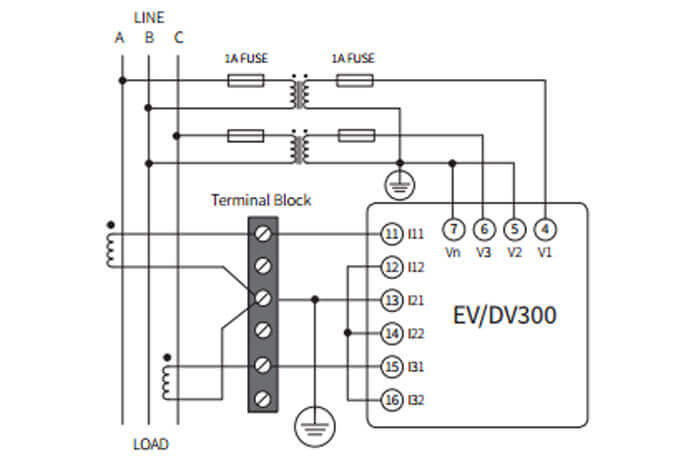
Figure 5: Meter configuration: 2LL, 2CT
Single Phase: 2 Lines (Single phase with one line and a neutral)
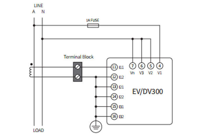
Figure 6: Meter Configuration: 1LN, 1CT
Single Phase: 3 Lines (Single phase with 2 lines and a neutral)
Figure 7: Meter Configuration: 1LL, 2CT
Power Supply Connection
Caution: Check the side of the meter to confirm what power supply option you have needed to power the meter.
The top of the meter contains a silver sticker which has information such as the model number, power supply, voltage/current inputs and serial number.
To power on the meter, you need to connect the power supply terminal, as shown below.
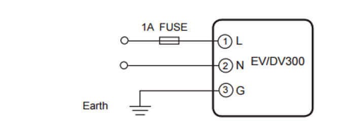
Figure 8: Power Supply Connection
This will be connected based on the following power supply options available, that is:
- The Standard option: 100-240Vac, 50/60Hz or 100-300Vdc