
How to View Energy Readings
- Press ‘E’ to display/read different energy readings such as consumed energy (kWh), energy, reactive energy (kvarh), generated energy (kWh), etc.
Note: The information on this screen will vary depending on the model number and firmware version of your meter.
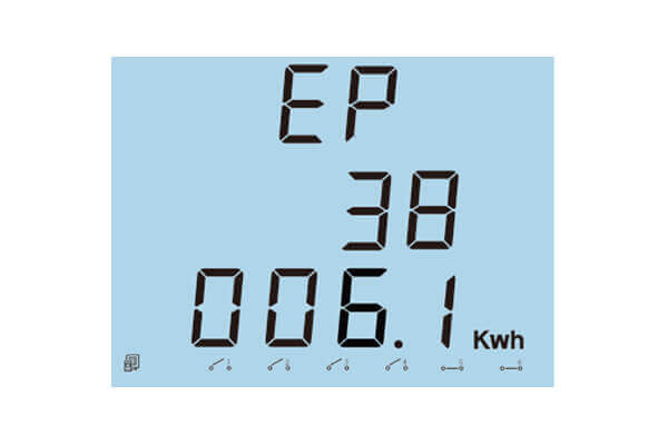
Figure 1: Consumed Energy
Ep= 38106.1 kWh. The maximum energy that can be accumulated is 99999999.9 kWh. After that the meter will roll over to 0.
How to View Measured Power
- Press ‘P’ to display the real, reactive and apparent power, as well as the power factor and frequency.
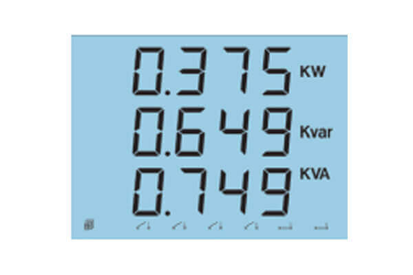
Figure 2: Power Readings Screen
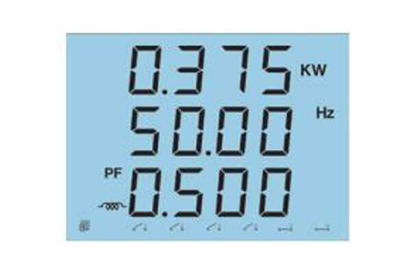
Figure 3: Frequency and Power Factor Readings Screen
How to View Voltage and Current Measurements
- Press ‘V/A’ to display the phase and line voltages, as well as the current readings. The last screen will display the average of the voltage and current.
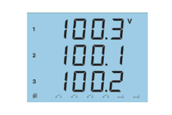
Figure 4: Voltage Reading Screen
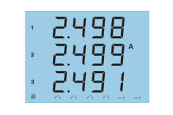
Figure 5: Current Reading Screen
How to View the DI Status
The DI status can be viewed from the bottom of the display on any screen in metering mode. DI1, DI2, DI3, DI4 are open status whiles DI5 and DI6 are closed status.
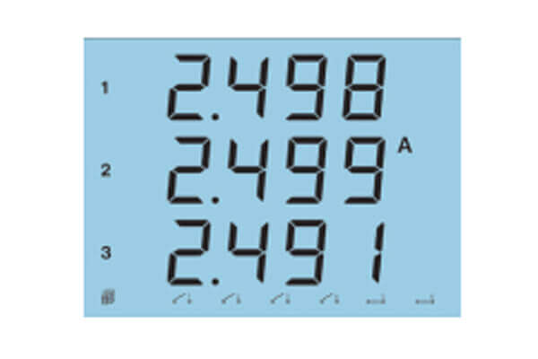
Figure 6: DI Status
Meter Settings
Note: Some of these settings will vary depending on the model number and firmware version of the meter
How to Access Meter Settings
You can change settings from the meter’s display by going to the Setting mode. Press ‘‹›’ and ‘V/A’ simultaneously whiles on the metering screen mode to get to the settings mode.
In the setting mode:
- ‘V/A’ can be used to confirm changes or go to the next screen
- ‘‹›’ can be used to change a setting or enter edit mode. A digit will begin to flash in edit mode. When in edit mode:
-
- Press ‘E’ to increase the value of the flashing digit
- Press 'P' to decrease the value of the flashing digit
- Press ‘‹›’ to switch the flashing digit
- Press ‘V/A’ on the last digit to confirm the change; the cursor should stop flashing.
-
Once you are in the settings mode, you will be required to enter a password on the ‘PASS’ screen.
- Enter your password or leave it as default ‘0000’ if it wasn’t changed.
- Press ‘V/A’ to enter the system parameter settings mode.
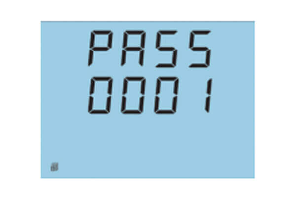
Figure 7: DI Status
How to Setup the Meter
For the initial meter setup, you will have to set the wire mode, PT and CT ratios. Here are the steps to follow to setup your meter from the display.
- Press ‘‹›’ and ‘V/A’ whiles in metering screen mode to get to the settings mode.
- A password screen will be displayed. Leave the password as default ‘0000’ and press ‘V/A’ to enter the setting mode; communication address ‘Add’ screen will be displayed.
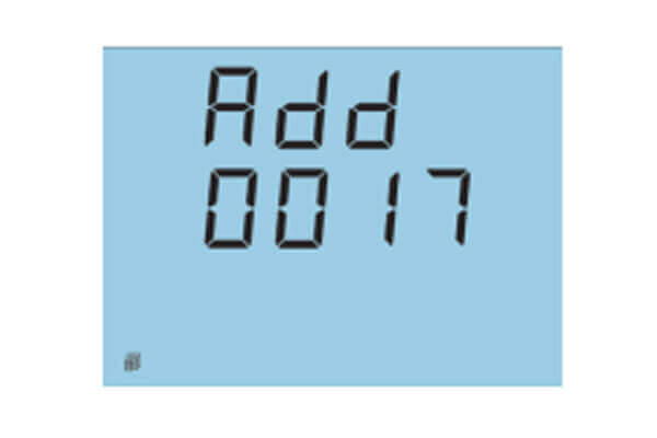
Figure 8: Device Address
Press ‘V/A’ until you get to the ‘Y1 Ⱶe’ screen. Select the required voltage wire mode. This will be based on your voltage connection. E.g. if it’s a three phase 4 wire connection, select ‘3LN’.
Check the Installation section or the user manual for more details
- Press ‘P’ or ‘E’ to select the required voltage wire mode.
- Press ‘V/A’ to confirm the change and move to the next screen.
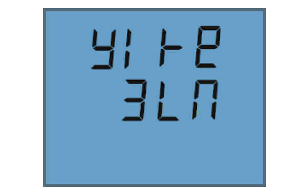
Figure 9: Wiring Mode
- The next screen is the PT1 screen. If no Potential Transformers (PTs) were used, leave this as default ‘220’ and press ‘V/A’ to go to the next screen. If PTs were used, enter in the primary value of the PT here.
Note: The top numbers on the screen are the most significant numbers to the bottom numbers. i.e. 0000 on the top and 220.0 below means 000220
- Press ‘‹›’ to switch the flashing digit.
- Press ‘P’ or ‘E’ to change the flashing digit’s value.
- Press ‘V/A’ to confirm the changes and move to the next screen.
- The next screen is the PT2 screen. If no Potential Transformers (PTs) were used, leave this as default ‘220’ and press ‘V/A’ to go to the next screen. If PTs were used, enter in the secondary value of the PT here.
- Press ‘‹›’ to switch the flashing digit.
- Press ‘P’ or ‘E’ to change the flashing digit’s value.
- Press ‘V/A’ to confirm the changes and move to the next screen.
- The next screen is the CT1 screen. If no Current Transformers (CTs) were used, leave this as default ‘5’ and press ‘V/A’ to go to the next screen. If CTs were used, enter in the primary value of the CT here.
- Press ‘‹›’ to switch the flashing digit.
- Press ‘P’ or ‘E’ to change the flashing digit’s value.
- Press ‘V/A’ to confirm the changes and move to the next screen
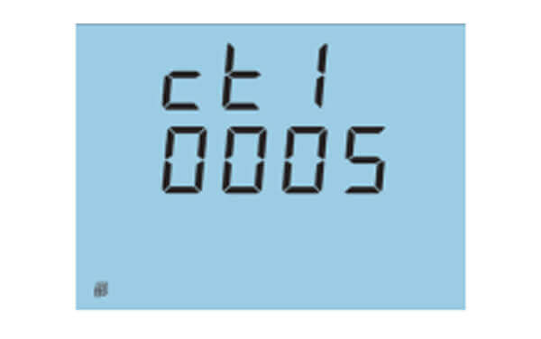
Figure 10: CT1 Setting
The next screen is the CT2 screen. This should already be set as the secondary value of the CT. After this is confirmed, you can return to the metering screen mode.
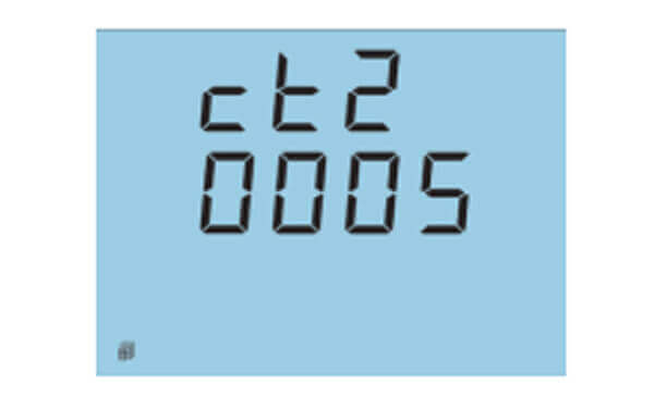
Figure 11: CT2 Setting
- Press ‘‹›’ and ‘V/A’ simultaneously to take you back to the metering screen mode.
The Initial Setup is now complete. You can begin to read the meter data accurately.
How to Configure the Digital Output Settings of the EV300
Note: This is only applicable to the EV300 series meter with the 'E2' or 'E3' options.
To get to the DO parameter settings screen:
- Press ‘‹›’ and ‘V/A’ whiles in metering screen mode to get to the settings mode.
- A password screen will be displayed. Leave the password as default ‘0000’ and press ‘V/A’ to enter the setting mode; communication address ‘Add’ screen will be displayed.
- Press the 'V/A' button until you get to the 'do' setting page.
The first screen related to the DO settings is the ‘do’ screen for the selecting the output mode of the DO.
- Configure this setting to '0' for Energy Pulse output
- Configure this setting '1' for alarm output

Figure 12: DO Mode
If the output mode is configured for Energy Pulse output, then the following screens will follow and will need to be configured:
- 'ECSⱵ' is the DO pulse constant. The pulse constant represents the relationship between the energy value(kWh or kVARh) and the pulse. The range of the pulse constant is from 800 to 60000 pulses.
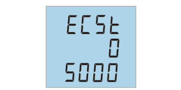
Figure 13: Pulse Constant
- 'PLS1' is the DO1 output parameter setting. The DO1 will only output a real energy(kWh) parameter. You can select:
- 'EPt' for total real energy
- 'EP-' for the generated real energy
- 'EP' for the consumed real energy
- 'PLS2' is the DO2 output parameter setting. The DO2 will only output a reactive energy(kVARh) parameter. You can select:
- 'Eqt' for total reactive energy
- 'Eq-' for the generated reactive energy
- 'Eq' for the consumed reactive energy
If the output mode is configured for alarm output, then the following screens will follow and will need to be configured:
- 'AL ⱵP' is the alarm output parameter setting. This indicates what parameter you will like to monitor for the alarm condition. Choose the parameter based on the numbers in the table below and enter that number.
| NO. | 00 | 01 | 02 | 03 | 04 | 05 | 06 | 07 | 08 | 09 |
|---|---|---|---|---|---|---|---|---|---|---|
| Parameter | None | V1 | V2 | V3 | V12 | V23 | V31 | I1 | I2 | I3 |
| NO. | 10 | 11 | 12 | 13 | 14 | 15 | 16 | 17 | 18 | |
| Parameter | Vavg | VLavg | Iavg | P(kW) | Q (kvar) | S (kVA) | F (Hz) | PF | In |
How to Configure the Analog Output Settings of the EV300
Note: This is only applicable to the EV300 series meter with the 'E3' or 'E4' options.
To get to the AO parameter settings screen:
- Press ‘‹›’ and ‘V/A’ whiles in metering screen mode to get to the settings mode.
- A password screen will be displayed. Leave the password as default ‘0000’ and press ‘V/A’ to enter the setting mode; communication address ‘Add’ screen will be displayed.
- Press the 'V/A' button until you get to the 'AO 1P' setting page.
The first screen related to the AO settings is the ‘Ao 1P’ screen for the selecting the parameter to output.
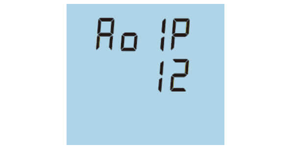
Figure 13: AO Parameter
- Enter the number of the parameter based on the numbers in the table below.
| NO. | 00 | 01 | 02 | 03 | 04 | 05 | 06 | 07 | 08 |
|---|---|---|---|---|---|---|---|---|---|
| Parameter | V1 | V2 | V3 | V12 | V23 | V31 | I1 | I2 | I3 |
| NO. | 09 | 10 | 11 | 12 | 13 | 14 | 15 | 16 | |
| Parameter | Vavg | VLavg | Iavg | P(kW) | Q (kvar) | S (kVA) | F (Hz) | PF |
- 'Ao 1o' is the AO output signal mode. Select '0' to output a 0-20mA signal or '1' to output a 4-20mA signal.
- 'Ao 1H' is for setting the AO1 upper limit. Enter the number in terms of a percentage. This setting can be configured from 0-120%.
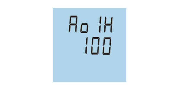
Figure 14: AO High Limit
'Ao 1L' is for setting the AO1 lower limit. Enter the number in terms of a percentage. This settings can be configured from 0-120%.

Figure 15: AO Low Limit
NOTE: Only when the P(kW) or Q(kvar) are chosen as the parameters to output then the 'sign' digit can be set for the upper and lower limits. The following settings will appear if these parameters are selected:
- 'o 1HS' is for setting the 'sign' for the upper limit. Select '0' is for positive or select '-1' for negative.
- 'o 1LS' is for setting the 'sign' for the lower limit. Select '0' is for positive or select '-1' for negative.
- 'Ao 2P' is for selecting the parameter to output. It is the same as AO1 above.
- 'Ao 2o' is the AO output signal mode. It is the same as AO1 above.
- 'Ao 2H' is for setting the AO2 upper limit. It is the same as AO1 above.
- 'AO 2L' is for setting the AO2 lower limit. It is the same as AO1 above.
How to Configure the Relay Output Settings of the EV300
Note: This is only applicable to the EV300 series meter with the 'E1' or 'E4' options.
To get to the RO parameter settings screen:
- Press ‘‹›’ and ‘V/A’ whiles in metering screen mode to get to the settings mode.
- A password screen will be displayed. Leave the password as default ‘0000’ and press ‘V/A’ to enter the setting mode; communication address ‘Add’ screen will be displayed.
- Press the 'V/A' button until you get to the 'Ⱶo' setting page.
Once on the 'Ⱶo' setting page choose the mode for the RO:
- Select '0' for the RO to work in Latch mode. In this mode the RO can be manually triggered using the EV300 series Utility software.
- Select '1' for the RO to work in Momentary mode. Once triggered on the RO will stay on for 800ms before closing. In this mode the RO can be manually triggered using the EV300 series Utility software.
- Select '2' for the RO to work in Alarm mode.
When the RO is configured in Alarm mode, the 'Alarm Limit' needs to be configured for RO1 or RO2.
- 'Ⱶo 1P' is the alarm output parameter setting. This indicates what parameter you will like to trigger for RO channel 1 when there is an alarm condition. Choose the parameter based on the numbers in the table below and enter that number.
| NO. | 00 | 01 | 02 | 03 | 04 | 05 | 06 | 07 | 08 | 09 |
|---|---|---|---|---|---|---|---|---|---|---|
| Parameter | None | V1 | V2 | V3 | V12 | V23 | V31 | I1 | I2 | I3 |
| NO. | 10 | 11 | 12 | 13 | 14 | 15 | 16 | 17 | 18 | |
| Parameter | Vavg | VLavg | Iavg | P(kW) | Q (kvar) | S (kVA) | F (Hz) | PF | In |
- 'Ⱶo 1U' is the alarm condition value for the parameter. Enter the value for when the parameter should go into alarm mode.
- 'Ⱶo 1t' is the time delay for how long the alarm condition must persist for before the alarm is triggered. The range for the time delay is from 0 to 255 sec.
- 'Ⱶo 1S' is the inequality sign setting. This is to set the alarm condition. Select '0' for less than (<) or '1' for greater than (>)
- 'Ⱶo 1o' is the RO output mode when in alarm. Select '0' to for the RO channel to work in 'Latch' mode when the alarm is triggered, or '1' to have the RO channel work in 'Momentary' mode when the alarm is triggered.
- 'Ⱶo 2P' is the alarm output parameter setting for triggering RO channel 2. It is the same as RO1 above when it is configured for Alarm mode.
- 'Ⱶo 2U' is the alarm condition value for the parameter. It is the same RO1 above.
- 'Ⱶo 2t' is the time delay for how long the alarm condition must persist for before the alarm is triggered. It is the same as RO1 above.
- 'Ⱶo 2S' is the inequality sign setting. This is to set the alarm condition. It is the same as RO1 above.
- 'Ⱶo 2o' is the RO output mode when in alarm. It is the same RO1 above.