Product Support
AcuRev 2000 Series Install Guide
Voltage and Current Connection
The AcuRev 2000 series can be installed using three common installation methods with the External CT (EM) Module or the Internal CT (DM) Module. The meter configurations and diagrams are displayed below.
Three Phase: 4 wire-connection (Three phase with a neutral)
External CT (EM) Module
The system you are monitoring has a voltage lower than 400V LN or 690V LL and you are using the DM Module current input, the connection diagram is shown below.
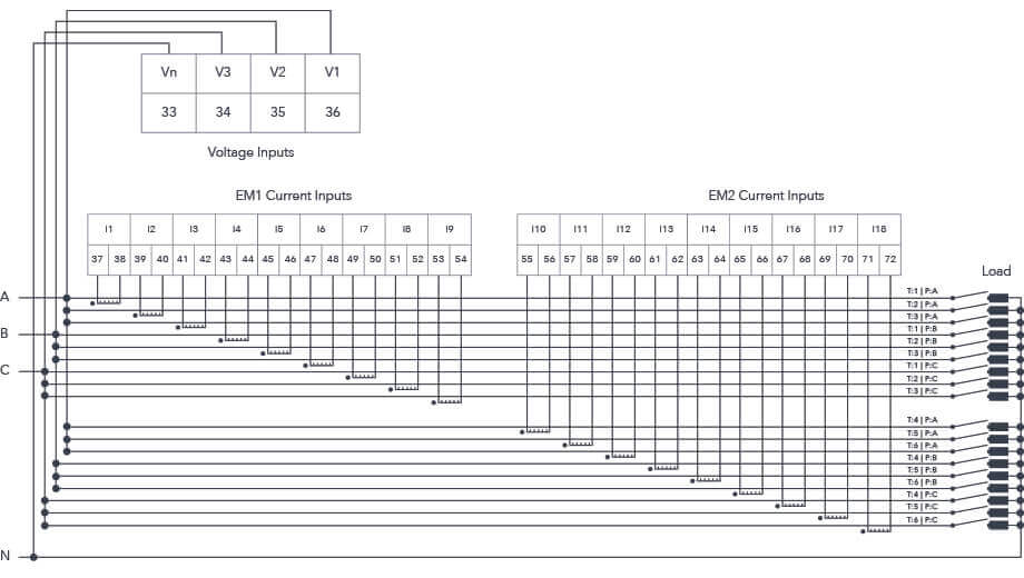
Figure 1: External CT (EM) Module Metering Configuration - 3LN
Internal CT (DM) Module
The system you are monitoring has a voltage lower than 400V LN or 690V LL and you are using the EM Module current input, the connection diagram is shown below.
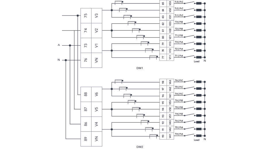
Figure 2: Internal CT (DM) Module Metering Configuration - 3LN
The relationship between the current input channels and each user is described below:
| Tenant 1 | Tenant 2 | Tenant 3 | Tenant 4 | Tenant 5 | Tenant 6 | |
|---|---|---|---|---|---|---|
| Phase A | I1 | I2 | I3 | I10 | I11 | I12 |
| Phase B | I4 | I5 | I6 | I13 | I14 | I15 |
| Phase C | I7 | I8 | I9 | I16 | I17 | I18 |
Single Phase: 2 Lines (Single phase with one line and a neutral)
External CT (EM) Module
Using the EM Module current input, the connection diagram is shown below.
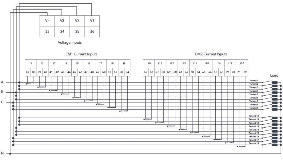
Figure 3: External CT (EM) Module Metering Configuration - 1LN
Internal CT (DM) Module
Using the DM Module current input, the connection diagram is shown below.
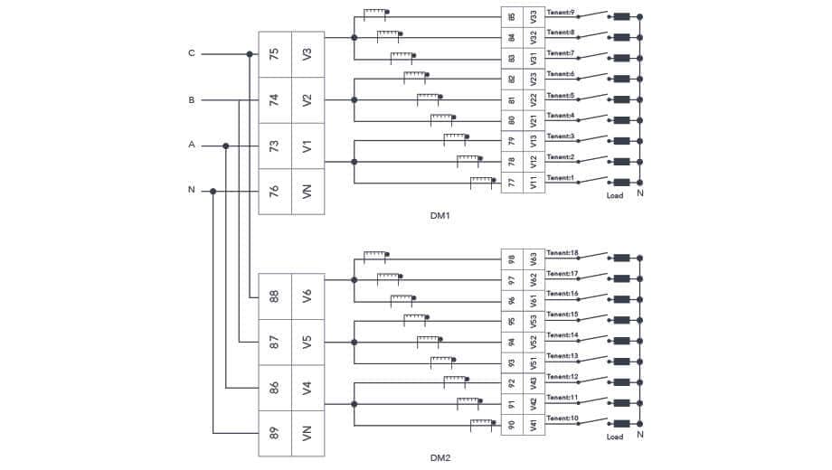
Figure 4: Internal CT (DM) Module Metering Configuration - 1LN
Single Phase: 3 Lines (Single phase with 2 lines and a neutral)
External CT (EM) Module
Using the EM Module current input, the connection diagram is shown below.
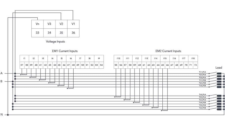
Figure 5: External CT (EM) Module Metering Configuration - 2LN
Internal CT (DM) Module
Using the DM Module current input, the connection diagram is shown below.
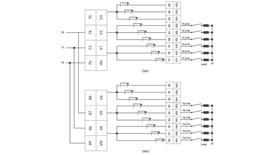
Figure 6: Internal CT (DM) Module Metering Configuration - 2LN
Power Supply Connection
To power on the meter connect the power supply terminal as shown in Figure 7
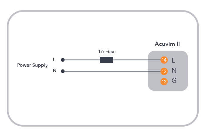
Figure 7: Power Supply Connection
