
-
What do I need to do for the initial set up and programming of my meter?
You will need to set the Voltage and current wiring mode, PT ratio and CT ratio. If no PTs were used, leave this setting as default. Information on the set up can be found in the ‘system parameter setting’ section of the user manual.
Also if communication is needed:
If Serial communication is to be used, you need to set the parity, baud rate and device address of the meter.
NOTE: The default parity, baud rate and device address can also be used.
If Ethernet communication is to be used, you need to set the network settings and the device address on the meter; also make sure the baud rate 2 is set as “38400” and parity 2 as “none 1”.
-
How do I know what wiring mode to select on the meter?
The wiring mode is based on your wiring configuration. You can find this in the “Wiring” section of the user manual.
-
I’m not able to read any three phase data, only the total of the three phases are shown?
When the system you are monitoring is using a three phase delta (3LL wiring mode) only the three phase total will be displayed on the meter. There are no phase readings because the system does not include a neutral, making all phase readings irrelevant in a 3 phase-no neutral delta system.
-
Where do I view the energy KWh consumption on the meter?
Acuvim II series:
The energy consumption can be found on the ‘imp kWh’ screen. This can be found by pressing the ‘E’ key one or more times on the meter screen.
Acuvim L series:
The energy consumption can be found on the ‘Ep imp’ screen. This can be found by pressing the ‘E’ key one or more times on the meter screen.
AcuRev 2000 series:
To view energy consumption on the AcuRev 2000 series, press the ‘left’ or ‘right’ key on the main screen until you select the ‘E’ option, after which you press ‘OK’.
AcuDC243:
The energy consumption can be found on the E1 screen. This can be found by pressing ‘V/A’ on the meter screen.
EV300:
The energy consumption can be found on the EP screen by pressing the ‘E’ button on the meter screen.
-
How do I get the monthly KWh consumption on the meter?
The meter displays accumulated energy reading. In order to know what the monthly consumption is, you can either take the readings from the previous month and subtract it from the current month OR reset the energy reading every month after noting down the energy consumption.
-
How do I clear my energy reading?
Energy reading can be cleared from the meter under the system parameter settings or from the software in the ‘Energy’ section under the ‘Readings’ tab.
Acuvim II series:
On Meter:
- Press ‘H’ and ‘V/A’ simultaneously for about 1 second; this will make the display blank, with a flashing cursor at the top.
- Move this cursor to ‘Setting’ by pressing ‘P’ or ‘E’, and then pressing ‘V/A’; a PASSWORD screen will be displayed.
- Enter your password by using ‘H’ to switch between digits, ‘P’ or ‘E’ to increase or decrease digits and ‘V/A’ to confirm password. NOTE: if you didn’t set a password, press ‘V/A’ on the password screen.
- The parameter selection mode is displayed with ‘SYS’, ‘I/O’, ‘NET’ and ‘ALM’ showing on the screen. The cursor will be on ‘SYS’; press ‘V/A’. This will take you to the parameter settings screen.
- Press ‘P’ or ‘E’ until you get to the ‘S22’ screen. NOTE: The number of the screen is on the top left corner of the screen.
- On the ‘S22’ screen, press ‘V/A’ to modify the clear energy setting, and then press ‘P’ or ‘E’ to change the option to ‘Yes’; press ‘V/A’ to confirm the setting. After this is done, the meter energy reading has been cleared.
- Press ‘H’ and ‘V/A’ simultaneously to make the screen blank, and then move the cursor to ‘Meter’ by pressing ‘P’ or ‘E’; press ‘V/A’ to go back to the meter screen.
On Software:
- For the Acuview software, click the ‘Real-Time Energy’ under the ‘Readings’ tab, and then click ‘Reset Energy’.
Acuvim L series:
On Meter:
- Press ‘H’ and ‘V/A’ simultaneously for about 1 second; this will take you to the password screen.
- Enter your password by using ‘H’ to switch between digits, ‘P’ or ‘E’ to increase or decrease digits and ‘V/A’ to confirm password. NOTE: if you didn’t set a password, press ‘V/A’ on the password screen. An ‘AddR’ screen should be displayed.
- Press ‘V/A’ until you see a ‘dEL E 0’ screen; this is the clear energy screen.
- Press ‘P’ or ‘E’ to change the ‘0’ to a ‘1’, then press ‘V/A’; this should take you to the ‘dEL E No’ screen.
- Press ‘P’ or ‘E’ on this screen to change the ‘No’ to ‘Yes’. Press ‘V/A’ to confirm this and the energy will be cleared.
- Press ‘H’ and ‘V/A’ simultaneously to exit the system setting mode and back to the meter mode.
On Software:
Click on ‘Energy’ on the ‘Readings’ tab, and then click ‘Reset Energy’.
AcuRev 2000 series:
On Meter:
- Press the ‘left’ or ‘right’ arrow key on the main screen until ‘SET’ is highlighted. Press ‘OK’
- A password screen is displayed. Enter the password by using ‘up’ or ‘down’ key to change the digits and ‘left’ or ‘right’ key to switch digits. When the password has been entered, press ‘OK’. NOTE: if no password was set, press ‘OK’ on the password ‘0000’ screen.
- Press the ‘left’ or ‘right’ key until you get to ‘P20’ screen with “TO CLEAR Energy NO” on the screen.
- Press ‘OK’ to make ‘Energy’ flash, and then press the ‘left’ or ‘right’ key to make ‘NO’ flash.
- Press ‘up or ‘down’ key to change the ‘NO’ to ‘YES’, and then press ‘OK’ to clear the energy.
- Press ‘left’ and ‘right’ key simultaneously for one second to return to the main screen.
On Software:
Click on ‘Energy’ under the ‘Readings’ menu. Click ‘Clear Energy’.
AcuDC 243
On Meter:
- Press ‘F’ and ‘V/A’ simultaneously for about 1 second; this will take you to the password screen.
- Enter the password by using ‘F’ to change digits and ‘V/A’ to confirm the flashing digit and move the cursor to the next digit. After the password has been entered, press ‘V/A’ to go to the next screen; if a password wasn’t set, press ‘V/A’ until you get to the next screen.
- Keep pressing ‘V/A’ until you see the ‘dEL No’ screen; press ‘F’ to change the ‘No’ to ‘Yes’ and press ‘V/A’ to confirm the clearing of energy.
- Press ‘F’ and ‘V/A’ simultaneously to get back to the metering screen.
On Software:
Click the ‘Real-Time Metering’ under the ‘Readings’ tab, and then click ‘Reset Energy’.
EV300:
On Meter:
- Press ‘‹›’ and ‘V/A’ simultaneously for about 1 second; this will take you to the password screen.
- Enter the password by using ‘P’ or ‘E’ to change digits and ‘V/A’ to confirm the flashing digit and move the cursor to the next digit. After the password has been entered, press ‘V/A’ to go to the next screen; if a password wasn’t set, press ‘V/A’ until you get to the next screen.
- Keep pressing ‘V/A’ until you see the ‘Ⱶ StE’ screen; press ‘‹›’ to enter edit mode and ‘P’ to change the ‘No’ to ‘Yes’ and press ‘V/A’ to confirm the clearing of energy.
- Press ‘‹›’ and ‘V/A’ simultaneously to get back to the metering screen.
On Software:
Click the ‘Real-Time Metering’ under the ‘Readings’ tab, and then click ‘Reset Energy’.
-
Why is the meter’s Current value (I) very small and Energy reading accumulating slowly?
Please check if the CT ratio is setup correctly on the meter. CT1 stands for the primary side of the CT ratio and CT2 is for the secondary side. For example, if the CT has a ratio of 400:5, you should enter 400 for CT1 and 5 for CT2.
NOTE: The CT1 screen on the Acuvim L series has two rows, and CT2 screen can be seen on the screen after CT1
-
Power shown on meter is negative but power factor is high, why is this so?
Negative power means your system is generating (delivering/exporting) energy. If your meter is monitoring a generator system, you should see negative power and this is correct. However, if your meter is monitoring a load that consumes energy, negative power (with high PF) usually results from 3 possibly reasons: the voltage and current are not aligned, the CTs are mounted in the reverse direction or the CT leads are wired to the meter in the opposite direction. Confirm that the voltage and current are aligned, for example, make sure phase ‘A’ correspond to voltage V1 and current I11 and I12 connections etc. Also make sure the P1/S1/H side of the CT faces the utility/source and that the black and white leads of the CTs are connected in the way specified by the CT manufacturer.
The Accuenergy 5A CTs requires the black go in first, that is, I11, I21, I31 should be black and I12, I22, I32 should be white, while the opposite colour code is used for Accuenergy 333mV CTs.
If Acuvim II series is used, you can reverse the CT current direction for each line from the system parameters setting mode instead of physically reversing the CT (this can be done on the meter or through the software).
NOTE:This can only be done if the alignment is correct and the CT direction or lead order is the only things wrong.
-
Why is the Power Factor low?
Please check voltage and current connections and make sure that voltage phase and current phase are aligned (i.e. phase A should correspond to voltage V1 and current I11 and I12 connections etc).
-
Does the meter support single phase application?
The meter supports single phase application (either single phase 2 wire or single phase 3 wire).
Old Platform: The wiring configuration should be set to 3LN and 3CT for both 2 wire and 3 wire single phase systems.
New Platform: The wiring configuration should be set to 1LN, 1CT for single phase 2 wire, and 1LL, 2CT for single phase 3 wire system.
-
Does the meter require external power supply?
The meter requires auxiliary power for its power supply. There are two power supply options available, the standard power supply option 100-415Vac or 100-300Vdc (100-240Vac or 100-300Vdc for AcuDC 240 series and EV300 series) and the low voltage power supply option (20-60Vdc). You can connect the power supply to a 120/240Vac outlet or connect it together with the voltage port (as long as the input voltage range is between 100 – 415 VacL-L) for the standard power supply option.
-
Can I use the voltage input for the control power of meter?
Yes you can use a jumper to power the meter as long as the voltage input is within the meters control power limit of 100-415Vac for P1 meters, and 20-60Vdc for P2 meters. V1 on the voltage input can be jumped to ‘L’ on the meters power supply terminal, and V2 of the voltage input can be jumped to ‘N’.
NOTE: If there is a neutral in the system you can jump the neutral from the voltage input to the ‘N’ terminal of the meters power supply, and use one of the voltage inputs to connect to ‘L’.
-
Is a power supply needed for Pulse Output?
A 24V DC power supply is required to generate the pulse output.
-
How to connect Pulse Output to pulse input?
In order to wire the pulse output correctly the following connections are to be made:
- A 24V DC supply is required to attain the pulse. The positive 24V must be connected to the Digital Output Common (DOC). A 1 kΩ resistor is required in series to limit the current from the 24V DC supply.
- The Digital Output 1(DO1) is connected to the positive terminal of the pulse counter
- The negative of the pulse counter is connected to the negative terminal of the 24V supply
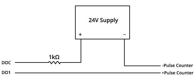
NOTE: If you have the Acuvim II, L, DC the terminals used on the I/O modules are DO1 and DOC. If using the AcuRev 1310 Series the terminals used on the meter are P2 and P1. If using the AcuRev 2000 series the terminals used are E and C.
-
What is the refresh rate of the meter screen and meter register?
(for 60Hz system) Acuvim || Series Acuvim L Series LCD Screen 1s 1s Modbus Data 100ms 1s -
What is the sampling rate per cycle of the meter?
II: 256 samples per cycle (old platform); 512 samples per cycle (new platform)
IIR/IIE/IIW: 512 samples per cycle (old and new platform)
L: 128 samples per cycle (old platform); 512 samples per cycle (new platform)
AcuRev 2000: 64 samples per cycle
-
What is the life expectancy of the meter and does it require recalibration?
Acuvim series meter has a life expectancy (MTBF) of 17.5 years and does not require recalibration. In general, digital power meters do not require recalibration, only analog meters require that.
NOTE: if you require re-calibration, you can send the meter back to us for NIST-traceable calibration service; certificate will be provided.
-
Do your meters support SunSpec?
The AcuRev 1310 and Acuvim II series support SunSpec.
The SunSpec registers can be found in the download section of our website, as well as the user manual for the meter also found in the downloads section.
-
Are the meters bi-directional?
Yes, our meters are bi-directional; they support bi-directional current measurement and can measure both consumed and generated energy.
-
Can I use the meter to monitor the load side of a variable frequency drive (AC drives)?
Acuvim series meter cannot be used to monitor the load side of an AC drive. It can be used to monitor the source side of the AC motor drive system. This will give an accurate consumption.
-
Can I use more than one type of CT for one meter and does it support multiple circuits?
Acuvim II, L and EV300 series meters are designed for single circuit applications; therefore, only one type of CT (with same CT ratio) can be used.
AcuRev 2000 series meter is designed for multi-circuit applications and different types of CTs with different CT ratios can be used.
-
What is the frequency range of the meter?
Acuvim II, L and AcuRev 2000 series meter supports frequency from 45Hz to 65Hz.
The Acuvim II series meter supports 400Hz, if needed.
New platform meters have auto-frequency adaptation: This means the meter can automatically detects the frequency of the electrical system.
-
What is the default password of the meter to enter the systems parameter settings page?
The default password of the meter is 0000.
-
Where can I setup the real time clock for the meter?
The meter’s real time clock can only be set via communication using the software, except on the AcuRev 2000 series meter in which it can both be set using the software and the meter.
Using the Software
After connecting the meter to the computer using the software, follow these steps to set the real time clock for the meter:
Acuvim II series and Acuvim L series (DL and EL only)
- Click on ‘System Status’ section under the ‘Readings’ tab.
- Select the method to set the clock (by using PC time or entering a date and time)
- Click ‘Set Device Clock’
AcuRev 2000 series
- Click on ‘Device Information’ section under the ‘Readings’ menu.
- Select the method to set the clock (by using PC time or entering a date and time)
- Click ‘Set Device Clock’
AcuRev 2000 series
- Press left or right on the main screen to have ‘SET’ highlighted. Press ‘OK’
- Enter the Password and Press ‘OK’ (if no password was created, press ‘OK’)
- Press any of the arrow keys until you get to the Time set ‘P32’ screen.
- Set the time and date by pressing ‘OK’ to go into editing mode, left or right key to switch flashing digits, and up or down to increase or decrease the number.
- Press ‘OK’ to confirm settings.
- Press ‘left’ and ‘right’ key simultaneously for about one second to return to the main screen.
-
What type of serial port does the meter use and does the meter support RS422 and RS232?
The meter supports 2-wire RS485 serial bus. The meter does not support RS422 and RS232.
NOTE: We have Pre-configured USB-RS485 converter in stock. Some generic RS485-USB converters are not guaranteed to work.
-
Where can I find the Modbus map of the meter?
The full Modbus map is included in the user’s manual of the meter, as well as the downloads section of the website.
NOTE: A copy of the Modbus address can be sent to you whenever needed.
-
My master supports holding registers in the range of 40001-49999 but the decimal equivalent does not fit in this range, what address should I enter?
Try polling the addresses in the 400000 range. The address to poll would then be the decimal equivalent plus 400000. You can also try using the offset of 1 making the address to poll be 400001 plus the decimal equivalent.
-
Do I need to do calculations after reading a parameter from a modbus register address?
Some parameters will require calculations after reading the values from the modbus register while others will not. It is stated in the user manual what parameters require calculations and the ones that don’t.
You can get in contact with us if you require assistance.
-
What kind of communication protocols does the meter support?
Acuvim-CL and KL supports Modbus-RTU, while Acuvim-DL and EL supports Modbus-RTU and PROFIBUS-DP/V0. Acuvim II series supports Modbus-RTU, DNP3.0-RTU, DNP3.0-TCP, BACnet-MSTP, BACnet IP; Modbus-TCP, HTTPS webpage, email SMTP, SNMP, SNTP, HTTP/FTP Post, Mesh, WiFi, and DNP3.0-IP; PROFIBUS-DP/V0 (Profibus option). AcuDC240 series supports Modbus RTU. AcuRev 2000 series supports Infrared, Modbus-RTU, Modbus-TCP, HTTPS, SMTP, SNMP, SNTP, HTTP/FTP Post, and BACnet IP.
-
What type of serial port does the meter use and does the meter support RS422 and RS232?
The meter supports 2-wire RS485 serial bus. The meter does not support RS422 and RS232.
NOTE: We have Pre-configured USB-RS485 converter in stock. Some generic RS485-USB converters are not guaranteed to work.
-
How many meters can I connect together serially and what is the max length of connection?
According to the RS485 specification, up to 32 meters can be connected to a single RS485 bus without repeaters. If you want to connect more meters on a RS485 bus, you can add RS485 repeaters to your RS485 network. A maximum of 247 slave nodes can be added to one RS485 line with repeaters. The overall length of the RS485 cable connecting all devices should not exceed 1200m (4000ft).
-
How can I connect the meter to a computer that does not have RS485 port?
A USB-RS485 converter or RS232-RS485 converter can be used if your computer is equipped with a USB port or RS232 port.
NOTE: We have Pre-configured USB-RS485 converter in stock. Some generic RS485-USB converters are not guaranteed to work.
Also, if you have an Ethernet module, a CAT5 cable can be used to connect with the computer directly.
-
How do I know if there is communication between the meter and the computer?
The communication icon blinks when the meter is communicating to the computer.
-
What are the pin outs for the serial communication port?
The RS485 terminal of the meter has 3 pins (14, 15, 16) or (1,2,3 on AcuRev). Pin 14 (A) is for differential + signal; pin 15 (B) is for differential – signal; pin 16 (S) is for shielding. Please make sure positive signals (+) are connected together and negative signals (-) are connected together.
NOTE: A pin-out diagram from our converter can be sent if needed.
-
Do I need different settings if I have more than one meter on the same RS485 line?
When multiple meters are connected to the same RS485 line, make sure all meters have the same baud rate and parity with different device communication addresses. By default, the meter’s baud rate is 19200, parity is none 1 and the device communication address is 1.
-
What will be the maximum number of Modbus repeaters can be allowed in a single network?
32 repeaters.
-
Why can’t I connect the meter to the computer?
Firstly, you need to make sure the USB-RS485 converter being used is accurately wired and working. We have USB-RS485 converters that are reliable.
Secondly, make sure you have the device address, baud rate and parity settings the same on the software as on the meter. Also confirm you have the right com port; this can be found in the ‘device manager’ settings on your computer.
Acuvim II Series:
To change/confirm the settings on your meter:
- Press ‘H’ and ‘V/A’ simultaneously for about 1 second; this will make the display blank, with a flashing cursor at the top.
- Move this cursor to ‘Setting’ by pressing ‘P’ or ‘E’, and then pressing ‘V/A’; a PASSWORD screen will be displayed.
- Enter your password by using ‘H’ to switch between digits, ‘P’ or ‘E’ to increase or decrease digits and ‘V/A’ to confirm password. NOTE: if you didn’t set a password, press ‘V/A’ on the password screen.
- The parameter selection mode is displayed with’SYS’,’I/O’,’NET’ and’ALM’ showing on the screen. The cursor will be on ‘SYS’; press’V/A’. This will take you to the parameter settings screen.
- The first screen’S01′ is the device address Note this down or change it to the desired address. To change it, press ‘V/A’ to make the cursor flash, ‘P’ or ‘E’ to increase or decrease the number, and ‘H’ to move the flashing cursor. After the address has been changed, press ‘V/A’ to confirm.
- Press ‘P’ to go to the ‘S02’ baud rate Note this down or change it to the desired baud rate. To change it, press ‘V/A’ to make the cursor flash, ‘P’ or ‘E’ to increase or decrease the number, and ‘V/A’ to confirm.
- Press ‘P’ or ‘E’ to go to the ‘S30’ parity 1 Note this down or change it to the desired parity 1 setting. To change it, press ‘V/A’ to make the cursor flash, ‘P’ or ‘E’ to increase or decrease the number, and ‘V/A’ to confirm.
- Press’H’ and ‘V/A’ simultaneously to make the screen blank, and then move the cursor to’Meter’ by pressing ‘P’ or’E’; press ‘V/A’ to go back to the meter screen.
After all the settings have been confirmed, open the Acuview software
- A ‘connection setting’ window opens, put in the right com port, baud rate and parity, and then click OK.
- An ‘Add device’ window opens, choose the right device type and device address, and then click OK.
- Click on the connect button located at the top left corner of the screen. NOTE: This is the yellow light bulb icon.
AcuRev 2000 series
To change/confirm the settings on your meter
- Press the ‘left’ or ‘right’ arrow key on the main screen until ‘SET’ is highlighted. Press ‘OK’
- A password screen is displayed. Enter the password by using ‘up’ or ‘down’ key to change the digits and ‘left’ or ‘right’ key to switch digits. When the password has been entered, press ‘OK’. NOTE: if no password was set, press ‘OK’ on the password ‘0000’ screen.
- A ‘P01’ screen is displayed. Press the right key to get to the ‘P02 COM ADDRESS’ screen. Note down the address or change it by pressing ‘OK’ to enter the editing mode, up or down key to increase or decrease the number, left or right key to change the flashing cursor and OK to confirm the change.
- Press the right key to get to the ‘P03 COM RS485’ screen. Note down the Baud rate and parity (FORMAT) or change them by pressing ‘OK’ to enter editing mode, left or right to switch between the two Baud rate and parity settings, up or down to change the setting property, and’OK’ to confirm the change.
- Press ‘left’ and ‘right’ key simultaneously for one second to return to the main screen.
After all the settings are confirmed, open the AcuRev 2000 Utility software.
-
- A ‘connection setting’ window opens, enter in the right com port, baud rate, parity, device address and Device Type. Once the settings are entered correctly click ‘OK’ to continue.
- Click on the connect button located at the top left corner of the screen, or click on’Start’ on the main menu toolbar and select’Connect’.
AcuDC 240 series
To change/confirm the settings on your meter:
- Press ‘F’ and ‘V/A’ simultaneously for about 1 second; this will take you to the password screen.
- Enter the password by using ‘F’ to change digits and ‘V/A’ to confirm the flashing digit and move the cursor to the next digit. After the password has been entered, press ‘V/A’ to go to the next screen; if a password wasn’t set, press ‘V/A’ until you get to the next screen.
- The device address ‘Add’ screen is displayed. Note down the address or change it by pressing ‘F’ to change the value and ‘V/A’ to switch the flashing digit and also to confirm the settings and move to the next screen.
- The baud rate ‘bPS’ screen is displayed. Note it down or change it by pressing’F’ and ‘V/A’ to go to the next screen.
- The parity ‘CHEC’ screen is displayed. Note it down or change it by pressing’F’ and ‘V/A’ to go to the next screen.
- Press ‘F’ and ‘V/A’ simultaneously to get back to the metering screen.
After all settings have been confirmed, open the Acuview software
- A ‘connection setting’ window opens, enter in the right com port, baud rate and parity, and then click OK.
- An ‘Add device’ window opens, choose the right device type and device address, and then click OK.
- Click on the connect button located at the top left corner of the screen. NOTE: This is the yellow light bulb icon.
EV300 series
To change/confirm the settings on your meter
- Press ‘‹›’ and ‘V/A’ simultaneously for about 1 second; this will take you to the password screen.
- Enter the password by using ‘‹›’ to change digits, ‘P’ or ‘E’ to change value of the digit and ‘V/A’ to confirm the flashing digit and move the cursor to the next digit. After the password has been entered, press ‘V/A’ to go to the next screen; if a password wasn’t set, press ‘V/A’ until you get to the next screen.
- The device address ‘Add’ screen is displayed. Note down the address or change it by pressing ‘‹›’ to enter edit mode and ‘V/A’ to confirm the settings and move to the next screen.
- The baud rate ‘bPS’ screen is displayed. Note it down or change it by pressing ‘P’ and ‘V/A’ to go to the next screen.
- The parity ‘PAⱵ’ screen is displayed. Note it down or change it by pressing ‘P’ and ‘V/A’ to go to the next screen.
- Press ‘‹›’ and ‘V/A’ simultaneously to get back to the metering screen.
After all the settings are confirmed, open the EV300 Utililty software
- A ‘connection setting’ window opens, enter in the right com port, baud rate, parity, device address and Device Type. Once the settings are entered correctly click’OK’ to continue.
- Click on the connect button located at the top left corner of the screen, or click on the ‘Start’ on the toolbar menu and select ‘Connect. NOTE: The connect button is the button with the red telephone icon.
-
How do I know if the Ethernet module is connected to the Acuvim II series meter correctly?
When the module is connected to the meter correctly, you should be able to see the communication icon
 (blink) and the Ethernet module icon
 (solid) showing at the bottom of the meter’s front LCD screen. Please make sure that the Ethernet module is installed on the back of the meter FIRST before other modules are attached.
 -
Why aren’t my network settings being saved after I configure them?
After making or modifying any network or communication settings a net reset of the communications module is required to ensure the settings are saved to the meter.
To reset from the meters display:
- Press ‘H’ and ‘V/A’ at the same time for a second and release. You will see meter flashing.
- Press ‘P’ or ‘E’ to move the cursor to ‘Setting’. Press ‘V/A’ to enter the settings.
- You will be prompted by a password screen. Enter the password if one is configured, otherwise leave the password as its default of ‘0000’ and press ‘V/A’ to continue.
- With the cursor on ‘SYS’ press either ‘P’ or ‘E’ to move the cursor to ‘NET’ and press ‘V/A’.
- Press either ‘P’ or ‘E’ to go to ‘N09 NET REST’. This is the net reset page of the meter.
- Press ‘V/A’ to enter the edit mode, and press either ‘P’ or ‘E’ to change the setting to ‘RESET’.
- Press ‘V/A’ to confirm the setting.
- Now you can go back to the main metering screen by pressing ‘H’ and ‘V/A’ at the same time for a second.
- Then press ‘P’ or ‘E’ to go to ‘Meter’ and press ‘V/A’ to enter the metering mode.
-
What is the default password for the Ethernet module?
The default password for the AXM-NET is ‘12345678’
The default password for the ‘Admin’ Access Level for the AXM-WEB-PUSH and AXM-WIFI is ‘admin’
The default password for the ‘User’ Access Level for the AXM-WEB-PUSH and AXM-WIFI is ‘view’
-
Why am I unable to connect to software even though I have all meter settings correctly set?
Firstly, make sure you ‘RESET’ the module on the NET RESET screen after you have changed the network settings on the meter; this will update the settings in the Ethernet module. Also make sure that the Baud rate 2 and Parity 2 in the system parameter settings of the meter are set to “38400” and “none1” respectively.
Secondly, make sure you have the right settings on the software before connecting; settings such as:
- IP address (default: 192.168.1.254)
- Modbus port (default: 502)
- Device type (e.g. Acuvim IIR)
- Device address (default: 1)
-
How do I connect my meter directly to my computer using a CAT5 Ethernet cable?
To connect your meter directly to a computer using a CAT5 Ethernet cable, you need to set the computer’s IP address within the same IP range as that of the meter, and also have the same subnet mask and default gateway as the meter; that is, you need to manually set the IP settings on the computer. This can be done through the LAN (Local Area Network) properties.
The table below gives an example of what the computer setting could be, with the given meter setting.
Meter Setting Computer Setting IP Address 192.168.1.254 192.168.1.100 Subnet Mask 255.255.255.0 255.255.255.0 Gateway 192.168.1.1 192.168.1.1 To manually set the IP settings on your computer, follow these steps:
- Go to ‘Network Connections’ setting on the computer. Disable the Wireless Network Connection and enable ‘Local Area Connection’. Right click on ‘Local Area Connection’ and click on ‘Properties’.

- In the ‘Local Area Connection Properties’, select ‘Internet Protocol Version 4 (TCP/IPv4)’, and then click ‘Properties’.

- After the settings have been entered, Click ‘OK’, and then click ‘OK’ again.

- After the computer has been set, you can connect your meter to the computer directly using a CAT5 Ethernet cable.
- Go to ‘Network Connections’ setting on the computer. Disable the Wireless Network Connection and enable ‘Local Area Connection’. Right click on ‘Local Area Connection’ and click on ‘Properties’.
-
What should I check if I am not able to view the meter via internet (external network)?
Please check if you can communicate with your meter in LAN (Local Area Network) by connecting the meter directly to the computer using a CAT5 Ethernet cable. (Look at the previous question)
If you are able to communicate with the meter in LAN connection with the correct settings, you should also be able to communicate in the internet (external network) environment.
Please make sure port forwarding is setup correctly in your router. The default Modbus port is 502 and the default HTTP port is 80. When setting up the meter’s network parameters, use internal network settings (i.e. internal IP address, subnet mask and gateway) instead of external settings (i.e. router’s external network parameters).
-
What needs to be different when accessing multiple meters?
When accessing multiple meters internally, within the network, the meters must have different IP addresses.
When accessing multiple meters externally, outside the network, the meters must have different Modbus port.
-
What are the passwords for the AXM-WEB-PUSH access levels?
The password for User access level is ‘view’.
The password for Admin access level is ‘admin’.
-
How to retrieve data logs?
The data logs can be retrieved and saved as a .CSV file by using an FTP client. The data log can be enabled in the Communication settings in the meters web interface.
The AXM-WEB-PUSH, AXM-WIFI and AcuRev 2000 with web option supports logging data onto its memory. Once this feature is enabled, the module can log up to 3000 days or 3000 months of data depending on the backup file length.
The AXM-WEB-PUSH can log data at intervals of time ranging from 15 seconds to 1 month.
- The ‘Datalog’ page can be found in the ‘Settings’ menu under ‘Communications’ in the meters web interface.
- Data Upload:To use the data log function to log data onto the module, select the ‘Enable’ option to view and configure the settings that are applicable.
- Once enabled the following settings can be configured:
- Log Start Time:Select a valid time for the meter to start logging the data.
- NOTE: The device clock of the meter should be correctly configured and up to date.
- Log Interval:Select how frequently the module will log the data to the file from the drop down list. The logging interval can be from 15 seconds to 1 month.
- Backup File Length: Select the length of the log file as either 1 day or 1 month of data from the drop down list.
- Backup File Prefix: Provide a name for the log file which will be appended to the beginning of the log file. By default ‘logger1’ will be appended to the beginning of the log file.
- SFTP Enable: In order to download the data log from the module, select ‘Enable’. The log file will then be downloaded using an FTP client with the following credentials:
- Host: sftp://IP addressof the meter
- Username:sftp user
- Password: accuenergy
- Port: 22
- By default the password for retrieving the backup log files is ‘accuenergy’. The user can configure any password or can reset to the default of accuenergy by clicking on the ‘Reset SFTP Password’.
-
What types of security does the AXM-WIFI support?
The AXM-WIFI supports WEP, WPA/WPA2-PSK
-
How to configure the Acuvim II meter to communicate with the AXM-WIFI?
The protocol of the meter needs to be configured to ‘WIFI’ in the meter settings. This can be done by:
- Pressing ‘H’ and ‘V/A’ simultaneously for about a second. You will see the screen go blank and ‘Meter’ will be flashing.
- Press either ‘P’ or ‘E’ to move the cursor to ‘Setting’. Press ‘V/A’ to enter the meter settings.
- With the cursor on ‘SYS’ press ‘V/A’ to enter the system settings.
- Press ‘P’ or ‘E’ until you reach the ‘S34 PROTOCOL2’ screen.
- Press ‘V/A’ to enter the edit mode, and press either ‘P’ or ‘E’ to change the setting.
- Once ‘WIFI’ is selected press ‘V/A’ to confirm the setting.
NOTE: only with Acuvim II meters that have firmware version 3.65 and higher.
-
How to connect when AXM-WIFI is in default AP mode?
To access the meters web interface in AP mode:
- On your computer, open the list of available networks. The SSID will appear as AXM-WIFI-(Serial Number of Module).
- The password for the SSID is ‘accuenergy’.
- Once connected enter the IP address 192.168.100.1
- The meters login to the web interface will be displayed.
- Log in under the ‘Admin’ access level, the password is ‘admin’.
- Once users can successfully access the web interface they can view meter data as well as configure and modify the user settings.
-
How to configure to Station Mode?
- Log into the web interface under the ‘Admin’ access level, the password is ‘admin’
- Next click on the ‘Settings’ menu and select ‘Communications’.
- Click on the ‘WiFi’ tab
- Under Mode select ‘Station’.
- If DHCP is set to manual, scroll down to IP and configure an IP address to access the meters web interface via WiFi.
- Ensure that the subnet mask, gateway, and DNS servers are all configured correctly.
- After all settings are made, click ‘Save’.
- Next a module reset must be performed. To reset the communications module click on the ‘Settings’ menu and select ‘Management’. Once on the Management page click on reboot communications module. Once the reset is performed you will be asked to login to the interface again.
NOTE: Depending on the firmware version of the module the Management page will say either ‘Reboot Communications Module’ or ‘Reset Communications Module’. Both perform the same function.
-
How to obtain IP address?
The IP address of the AXM-WiFi can be obtained by viewing the N11 IP page in the meters NET Settings. To view the N11 page:
- Press ‘H’ and ‘V/A’ simultaneously for a second and release. The screen will go blank and ‘Meter’ will be flashing.
- Press ‘P’ to move the cursor to ‘Setting’.
- Press ‘V/A’ to enter, you will be redirected to a password screen.
- Enter in your password if one is configured otherwise leave it as the default of ‘0000’ and press ‘V/A’ to continue.
- Press ‘P’ to move the cursor down to ‘NET’, press ‘V/A’ to enter the NET settings.
- The first screen is ‘N01 DHCP’, press ‘P’ or ‘E’ until the ‘N11 IP’ screen is reached.
-
How to add a meter? Admin access is required to add a meter to AcuCloud. Also the AXM-WEB-PUSH firmware version must be v1.05 or higher. The process to add a meter requires the user to add the device to AcuCloud and obtain a token which will act as a verification when sending data from the Acuvim II meter. The token will be used to configure the meter from the AXM-WEB-PUSH or AXM-WIFI web interface. The following is the procedure to add the device to AcuCloud:
- Log in to AcuCloud with sufficient access to add new devices.
- Click on the ‘Devices’ tab on the left panel of AcuCloud.
- On the Devices page select ‘+ NEW DEVICE’.
- The following details need to be entered:
- Select the name of the facility in which the device belongs to from the Facility drop down list.
- Select the model of the device from the Model drop down list.
- Provide a name for the device under Device Name.
- Enter the serial number of the AXM-WEB-PUSH or AXM-WIFI module under Serial Number (found on the module itself or from the web interface in the Device Information page). The Serial number must be entered in Upper Case.
- Provide a description for the location of the device under location.
- Click SUBMIT.
- Once the device has been successfully created, a token will be returned on the ensuing page.
- Users will need to copy the token and use it in the web interface configuration.
- Access the web interface of the module by entering the IP address of the meter.
- Log in to the web server with Admin access level, the password is ‘admin’.
- Next click on the ‘Settings’ menu and select ‘Communications’.
- Select the ‘AcuCloud’ tab and click on ‘Enable’ under AcuCloud Reporting.
- Under AcuCloud URL enter in the following: https://acucloud.accuenergy.com/api/v1/devices/newdata
- Paste in the token received in the steps above under AcuCloud Token. Then click on ‘Save’
- The last step involves rebooting the communications module to ensure the settings are saved to the meter. This is done from the management page of the web server.
- Click on the ‘Settings’ menu and select ‘Management’. Click on ‘Reboot Communications Module’. NOTE: depending on the firmware of the module this setting will say ‘Reboot Communications Module’ or ‘Reset Communications Module’ both perform the same function.
-
I can’t add my meter to AcuCloud?
Ensure that you are signed up with AcuCloud before trying to add a meter. You can sign up through the following: AcuCloud
-
How to read the Energy data?
Energy data can be read by using the Energy Analysis on AcuCloud. You can access the Energy Analysis of your entire Facility or a device within your Facility. Viewing the Energy Analysis of a device:
- Find and click on the drop down list under your Facility name on the left panel of AcuCloud
- Select the device you wish to read the energy from. You will be directed to a page that provides an overview of your device.
- Click on the ‘Energy’ tab to access the Energy Analysis page.
- On the Energy Analysis page select the required time/date under the ‘Select a Time Frame:’ option.
- Then select the required energy parameter, and select whether to view phase or system readings.
- Once all desired settings are configured click on ‘UPDATE CHART’.
- The energy will be displayed in a bar graph format, and at the bottom of the page it will give a summary of the energy by providing the highest reading, lowest reading, average(mean), and the total energy consumption.
Viewing Energy Analysis of the Facility:
- Click your Facility name on the left panel of AcuCloud
- You will be directed to a page that provides an overview of your Facility.
- Click on the ‘Energy’ tab to access the Energy Analysis page.
- On the Energy Analysis page select the required time/date under the ‘Select a Time Frame:’ option.
- Then select the required energy parameter, and select whether to view phase or system readings.
- Once all desired settings are configured click on ‘UPDATE CHART’.
- The energy will be displayed in a bar graph format, and at the bottom of the page it will give a summary of the energy by providing the highest reading, lowest reading, average (mean), and the total energy consumption.
-
How to export data?
Users can export data by clicking on ‘Export Data’ on the top right corner of the home page on AcuCloud. Users can then choose the facility, device, and the required parameters. Also select the logging time for which the data is needed. One all required information is completed users will be able to download the data logs through a download link.
-
How to set alerts?
To access the alerts, click on the ‘Alerts’ button on the top right corner of the AcuCloud homepage. Users we be redirected to a page showing all alerts configured. To create a new alert click on ‘Add New Alert’. The following will explain how to configure the Alerts:
- Select the device you wish to set the alert for under ‘Choose a Device’
- Under ‘Type’, there are three different kinds of Alerts you can choose from:
- Flat line: is when there is no change/accumulation in the EP_IMP_kWh (consumed energy), with this alert type you can configure the time duration the flat line lasts before an alert is sent out.
- Offline: An Offline alert is sent out when the meter is no longer online and no data is received by the server. With this alert type you can configure the time duration this lasts before an alert is sent out.
- Parametric: A parametric alert is when you choose a specific parameter (i.e. Phase A voltage, total current, etc) and the selected parameter is over or under the threshold value an alert will be sent out. You can choose from energy, I/O, and real time metering parameters.
- NOTE: When creating an alert for a Calculated Meter, the only type of alert that can be created is Parametric.
- Enter in an email address so you can be notified when an alert has taken place.
- Once all the alert settings are configured click ‘SUBMIT’.
The AcuMesh wireless RS485 transceiver works like an “invisible wire”. It is intended to replace a traditional, wired RS485 network in a building or facility, reducing a significant amount of installation time, cost, and difficulty.
-
Which model is a transmitter, receiver and repeater?
Typically, a transmitter, receiver, and repeater are separate units in a wireless system. Unlike other wireless solutions, AcuMesh wireless transceiver has all three functions built in, so it works as transmitter, receiver and repeater from every single unit. The transceiver will automatically switch roles in the system. Each unit is capable of connecting to either master or slave RS485 devices to send and receive data/commands, and broadcast or repeat the command until every transceiver in the field is connected.
-
Can I connect more than one units to one AcuMesh transceiver?
Yes, just like physical wire where you directly connect a daisy chain of RS485 devices to another unit or master device. One AcuMesh transceiver is connected at the end of one chain of RS485 devices, and another transceiver connect to another group of device or master device.
-
What protocol does it support?
AcuMesh transceiver is compatible with Modbus-RTU over RS485.
-
If the two transceivers are not able to connect to each other due to distance, can I add another transceiver between, as a repeater, without connecting to an RS485 device?
Yes, once it is powered up, the AcuMesh transceiver will automatically act as a repeater to broadcast data across the private wireless mesh network.
-
Our application requires multiple groups of wireless networks, and they cannot interfere with each other or communicate with each other. Can the networks be configured this way?
Yes. The AcuMesh transceiver uses a default channel out of the box; you won’t need to do any additional configuration to connect all devices within a single network. If you need multiple networks that are separate from each other, simply configure a different channel name for the transceivers in the second network group. AcuMesh transceivers will only identify other devices with the same channel name. Additionally, each channel allows for a separate password for better security and management.
-
If the master device is a computer, do you offer a RS485 to USB converter?
Every AcuMesh transceiver has a built-in RS485 port and a USB port. In this case, you can either connect the RS485 port to any RS485 devices or connect via USB to a computer. When you connect via USB, the unit is capable of being powered by USB, so no external power supply would be needed.
-
Do you need to assign an address to each transceiver?
Since AcuMesh works via transparent communication, it does not add or modify Modbus-RTU protocol. Think of it as operating the same as a wired Modbus-RTU connection. A master device, whether it is a data acquisition server, a computer running master software, or a PLC will remain the same without any separate configuration required for the wireless connection. RS485 slave devices or sensors maintain their settings as well, such as Device ID.
-
How many AcuMesh transceivers can I connect in one network?
There is no limit to the number of AcuMesh transceivers that can be added to a single wireless mesh network. The limitation is imposed by the Modbus-RTU protocol. For example, Modbus-RTU daisy chain topology has a limit of 32 devices without a repeater.
-
How do I power up the AcuMesh transceiver?
The AcuMesh transceiver can be powered up using a 24Vdc supply. If connecting the transceiver to a computer, the 24Vdc is not required and can be powered by the provided USB cable.
-
What is the difference between the AcuMesh-L and the AcuMesh-K?
The only difference between the AcuMesh-L and AcuMesh-K transceivers is the form factor, the AcuMesh L is DIN rail mounted and the AcuMesh-K is surface mounted.
-
How many modules can be attached to the meter?
- A maximum of 3 modules may be attached to the meter.
- If a communication module is used (e.g. AXM-WEB-PUSH), it must be installed on the back of the meter FIRST before other modules are attached.
- There can only be one communication module connected to the meter
- No more than 2 of the same I/O modules may be attached to the meter. The same two IO modules must have different component number, for example, 2 AXM-IO2 will be AXM-IO2-1 and AXM-IO2-2 (please see ordering information in the brochure for more details).
-
Do I need to power off the meter before installing the modules?
Modules must be installed before powering on the meter.
-
Where can I find the user’s manual for the meter and modules?
User’s manual for the meter and modules are available here.
-
What is the default password of the meter to enter the systems parameter settings page?
The default password of the meter is 0000.
-
Why is the current 10 times bigger than what it should be after setting up the meter?
Please check the CT ratio and CT1 setting. The meter uses 4 digits on the top row and 1 digit in the middle for setting up parameters for CT1. When you have a CT ratio of 450:5, CT1 should read 0045 on the top line and 0 on the next line. CT2 is fixed at 5 (or 1 for the 1A option meter).
-
Energy readings are alright at first; however it seems to reset itself after a while. All the settings look correct and no resets have been performed. What can the problem be?
The Acuvim-L series meter utilizes all 3 rows of the digit display to show kWh/kvarh/kVA values. As the accumulated energy increases, the most significant digit (digit with the highest order) will move upwards. For example, for 98,765,432.1kWh, the meter will show 9 on the top line, 8765 in the middle and 432.1 at the bottom.
-
Why can’t I view all the three phases at once for a three phase user on the software?
Make sure you have the ‘wiring of the Three-phase User’ set as 3LN and the user channel as a number between 19 and 24 on the meter or between 301/201 and 306/206 on the software to represent the six three-phase channels the meter can measure.
To set this up on the meter:
- Press left or right on the main screen to have ‘SET’ highlighted. Press ‘OK’
- Enter the Password and Press ‘OK’ (if no password was created, press ‘OK’)
- Press any of the arrow keys until you get to the wiring mode ‘P29’ screen. Change the wiring mode to ‘3LN’ by pressing ‘OK’ to enter editing more, any of the arrow keys to change the setting to ‘3LN’ and ‘OK’ to confirm the change.
- Press any of the arrow keys until you get to the channel setting ‘P30’ screen. Press ‘OK’ to enter editing mode, left or right key to switch between ‘Name’ and ‘Channel’, up or down key to change the specific name or channel.
- When you have selected the appropriate user, change the user channel to a number between 19 and 24. Press ‘OK’ to confirm the setting.
To set this up using the software:
- Go to the ‘User and CT Settings’ under the ‘Settings’ menu.
- Select the ‘Wiring of Three-phase User’ as ‘3LN’
- Under ‘User and Channel Mapping’, choose the appropriate user and select the ‘Channel’ between “301/201 and 306/206”.
- Click ‘Update Device’.
-
How do the current input channels correspond to the voltage input?
The three phase wiring for the AcuRev 2000 series:
Channel 1 Channel 2 Channel 3 Channel 4 Channel 5 Channel 6 AcuRev 2020 Current Input Channels Phase A 1 2 3 10 11 12 Phase B 4 5 6 13 14 15 Phase C 7 8 9 16 17 18 -
What is the rated voltage in the General Settings of the AcuRev Utility Software for?
By default this value is configured to 220V and it affects any parameter that uses voltage in the alarm function. This configuration does not affect the meters ability to measure the voltage.
-
Why is the alarm set point in terms of percentage?
It is expressed by a percentage of the rated value for that parameter. For example the rated voltage is 220V and the set point is expressed as a percentage of that value.
The set point of the current is defined as a quarter of the full scale current. So if the current rating is 60A, a quarter of that is 15A. Therefore to set an alarm for when the current is greater than 15A the set point would be 100.
-
Why can’t I change any settings on the meter?
The AcuRev 1310 has a sealing function, check to see if whether the meter has the seal installed.
-
Why does it show Seal Status as ‘Sealed’?
Meter most likely has the seal installed on the meter if the hardware version is 2.03 or higher
For meters with hardware version 1.01, the sealed status will show if the terminal covers of the meter are installed.
-
How to read incorrect wiring detection function?
The wiring detection can be found on the meter by pressing and holding the ‘SCROLL’ button. The voltage wiring is identified by a ‘U’, and the current wiring detection is identified by an ‘I’. The format of the wiring detection is:
U XXXXXX, where X is either ‘1’ or ‘0’.
- ‘0’ represents the connection is correct
- ‘1’ represents the connection is incorrect.
If there are no errors the screen should read ‘U 000000’ for voltage and ‘I 000000” for current. On the meter display digits 1~3 (from left to right) would represent if a phase is not connected;Phase A Voltage missing, Phase B Voltage missing, Phase C Voltage missing. Digits 4~6 represent Phase A Voltage, Phase B Voltage, Phase C Voltage being connected incorrectly. For the Current detection, o the meter display digits 1~3 (from left to right) represent Phase A CT, Phase B CT, Phase C CT being in the reverse direction. Digits 4~6 represent Phase A CT, Phase B CT, Phase C CT being connected incorrectly.For example if the voltage wiring detection read ‘U 110000’, this would mean that the Phase A and Phase B voltage connection is missing.
-
Why do I only see kWh on the meter display?
By default the AcuRev 1310 series displays the total kWh reading. If you wish to see other parameters they can be added through the AcuRev 1310 Utility Software in the General Settings under the ‘Displayed Scan Parameters’ section.
Once the parameters are added, press ‘SCROLL’ on the meter to cycle through the selected parameters.
-
What is the direct input voltage and current range?
The input range for direct voltage measurement is 0-1000V and for current is 0-±10A.
-
Why does the DC meter show 0A when using a Hall Effect sensor?
Ensure the Hall Effect sensor has the required power supply (±15 Vdc). If the Hall Effect sensor has the required power supply then ensure the output of the sensor is wired correctly:
- Terminal 3 on the sensor is for output, ensure this is connected to ‘I+(5)’ on AcuDC 240 serie meter.
- Terminal 4 on the sensor is the ground, ensure there are two wires from this terminal; one going to ‘I-(6)’ on the AcuDC 240 series meter and the other wire must be grounded in order to see an output.
-
What are the differences between Hall Effect sensor and a shunt?
A Hall Effect sensor requires a power supply (±15 Vdc) while a shunt does not. Also, a shunt requires you to break the circuit to install while a Hall Effect sensor does not.
Make a comparison chart of both instruments.
Intrusive Power Supply Hall Effect Sensor Does not require breaking circuit to install Requires ±15 Vdc power supply Shunt Requires breaking circuit to install Does not require power supply
-
What side of the CT should face the utility?
The side of the CT that says P1/S1/H/h2 should face the utility side.
NOTE:Some CTs like ours, have arrow pointing in the direction of current flow.
-
How should the CT wires be connected to the meter?
5A Accuenergy CTs: The CT black lead should go in first before the white lead, that is black should go in to I11 and white to I12, black to I21 and white to I22, and black to I31 and white to I32.
333mV Accuenergy CTs: This is opposite to the case of the 5A CTs, that is, the CT white lead should go in first before the black lead.
Rogowski Coil (RCT) Accuenergy CTs: The CT’s white lead should be connected to I11 and brown lead should be connected to I12, white to I21 and brown to I22 and so forth. The shield wire can be grounded or left unconnected.
For AcuRev 2000 series, which uses the 333mV CTs, white will go into 37 and black to 38, white to 39 and black to 40 etc.
If AcuRev 2000 series is used with Rogowski Coil CT’s, the white lead will go into 37 and brown to 38, and so forth.
NOTE:All CT manufacturers do not have the same standard; use the right wire connection standard for the particular CT.
-
Do I need to ground the negative lead of my CT?
A Hall Effect sensor requires a power supply (±15 Vdc) while a shunt does not. Also, a shunt requires you to break the circuit to install while a Hall Effect sensor does not.
For the Rogowski coil, 333mV, and mA current transformer you should never ground the negative lead. The leads from these CTs can be connected directly into the terminal of the meter. Example:

-
Do I need to use shorting blocks?
Shorting blocks are only needed if the CT output is 5A/1A.There is no need to use shorting blocks for the Rogowski Coil, 333mV, and mA current transformers.
-
What are the different Panel boxes available and what are the differences?
We have the NEMA4 and NEMA4X panel boxes. The NEMA4 box is made of steel while the NEMA4X box is made of plastic. NEMA4 Panel box is an indoor panel box while the NEMA4X panel box is waterproof. A comparison table is shown below.
AcuPanel 9104 (NEMA 4) AcuPanel 9104X (NEMA 4X) Weight 18 lbs 7 lbs Water-Proof No Yes Anti-Corrosive No Yes Outdoor Installation No Yes Material Steel Polycarbonate Dust-Proof Yes Yes Indoor Installation Yes Yes -
Are the AcuPanel enclosures pre-wired?
The AcuPanel 9104 and 9104X are pre-wired and include fuses, shorting and terminal blocks. The AcuPanel 9106X is pre-wired and includes fuses and terminal blocks for voltage inputs. All wiring is clearly labeled by the factory.
-
-
Where can I download your software?
Our software can be downloaded on our website here.
You can also contact the technical service department to have it sent to your email.
-
What are the differences between Acuview software and the utility software?
Acuview Software Utility Software Supports multiple series meters Yes No (supports a specific series meter) View multiple devices at a time Yes No Setting up for data logging on meter memory Yes Yes Setting up for data logging on Computer memory Yes No Reads all on-board data log entries in the meter memory Yes (reads 64000 on-board data log entries) Yes -
Does the Acuview and utility software accept both serial and Ethernet connection?
Yes. You can connect your meter to Acuview by using serial communication or Ethernet connection.
-
How should I add my meter to Acuview?
You can add a meter to an available connection by clicking the “Add Device” icon. Please make sure to select the correct connection name (IP address or COM port), Modbus port and device communication address for each device.
-
How to view multiple meters at the same time?
To view and monitor multiple meters at a time using the AcuView software, all meters need to have an available connection first before adding the meters.
- Create a ‘Connection’ to each meter either serial or network.
- Press ‘Add Device’ and add all the meters to the software based on the ‘Connection’ just made.
- Press ‘Connect’ so that the software will connect to each meter all at once.
- Click on ‘Window’ to select a viewing option for all the meters that the software is connected to.
- NOTE: Only one meter can be viewed at a time using a meters Utility Software.
-
What are the computer system requirements for Acuview?
Operation System:Windows 2000/XP/Vista/7/8/10
RAM: 128MB/256MB or More
Hard Disk Space: 100 MB/500MB or More
Display: 1024×768 or Higher
Software Installed: Microsoft Office Excel 2000/XP/2003/2007
If Microsoft Excel is not installed in the system, the log files cannot be saved as Excel documents.
-
What kinds of meters are supported by Acuview?
Acuview supports Acuvim DX, Acuvim EX, Acuvim FX, Acuvim GX, Acuvim CL, Acuvim DL, Acuvim EL, Acuvim KL, Acuvim II, Acuvim IIR, Acuvim IIE, Acuvim IIW, Acuvim, Acuvim+, AcuDC 240 series, AcuDC 220 series.
-
Can I replace the utility software with Acuview?
Yes, if the meter is supported by Acuview, you can replace its utility software with Acuview.
-
What happens when the meter memory is full during data logging?
If the ‘Logging Timer’ is disabled for data logging, a ‘sector’ will be deleted once the meter memory isi full.
If the ‘Logging Timer’ is enabled, data logging will stop once the memory is full.
-
Data isn’t logging when ‘Logging Timer’ is enabled. Why is this so?
This can be because the date and time are not set. Make sure this is set in the ‘system status’ section of the software.
-
Can I data log directly on my computer?
Yes, you can data log directly on your computer using the Acuview software; this can be found in the data log settings or by pressing Ctrl+L. The meter would have to be connected to the computer with the software open for data to be logged.
-
Can I view the Excel file when data logging is running?
You can view the Excel file; however, do not double click on ANY Excel files when data logging is running. To open and view the spreadsheet, run Excel and open the data logging file from Excel.
-
Why is my data log file not updating on my computer, but the ‘Monitoring time Used’ on the data log settings on Acuview keeps increasing?
The reason for this might be that the customer had double clicked on the data log file while it was running instead of opening through excel i.e. open excel software and then open file.
-
Can I modify the data log file name and can I save the file on a network drive?
Yes, you can create your own data log file name and save the file on any directories (including network drives that have been mapped to the computer). Each data log file has a time-stamp postfix attached to the file name.
Follow these steps to do this:
-
- Open the Acuview software and enter the necessary connection settings and device information. Click ‘Connect’.
- After the meter is connected, go to ‘Settings’ on the menu bar at the top of the software screen. Click ‘Data Log Settings’.

-
- In the ‘Data Log Settings’, check the ‘Enabled’ box to enable data logging, check the required ‘Logging items of Selection’, enter the ‘Logging Options’.

-
- Enter the file name required, under the ‘Log file name’; also choose the location to save the file under ‘Log file folder location’.
- Click ‘OK’ after you are done.

-
-
Can I view setting files (pmt files) without connecting the meter to the software?
Pmt files can be viewed without a meter connected to the software. This can be done by opening the file in Microsoft word or Notepad. It can also be opened using a web browser.
-


