Product Support
Configure Utility Software for use with AcuRev 2000
Configure the General Settings of the AcuRev 2000
- Click on "Settings" located on the upper menu and then select "General Settings" to view and change different system settings such as meter password, communication address, baud rate, rated voltage and etc.
Make sure to click "Update Device" after making any changes, so that the changes can be saved on the meter.
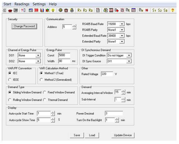
Figure 1: General Settings
Configure Current Channels on AcuRev 2000
- Click on "Settings" from the upper menu and then select "User and CT Settings" to configure the CT settings.
Under "User and Channel Mapping" you can configure the:
- User name: Assign a name to each channel up to 6 characters
- Channels: Correspondence between the user and the current input channels of the meter. You can select "101-118" if the users are single phase or "301/201-306/206" otherwise; these numbers represent the 18 single phase channels or the 6 three phase channels.
- Enable display: If a channel is being used click on the "Enable display" box, otherwise leave the box unchecked so the corresponding channels will not be displayed.
Select the "Wiring of Three-phase User":
- You have the option for three phase, two phases or single phase wiring.
- CT model: When using the EM modules different channels can access different current transformer ratios, enter the rated input or select from the dropdown box.
Make sure to click "Update Device" after making any changes in order to save the settings.
For convenience, you can also save and load these settings on to other AcuRev meters.
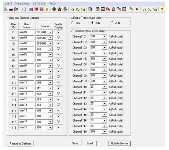
Figure 2: User and CT Settings
Configure Software I/O Settings for AcuRev 2000
- Click on "Settings" from the upper menu and then select "DI, RO and Event settings" to configure the settings related to the Digital Input and Relay Output.
Digital Input Settings
The eight Digital Input (DI) channels can be configured as either a signal switch status monitor (state mode) or Pulse counter (counter mode)
If the DI channel type is configured in state mode then:
- "ON" displays when the signal is on a high level.
- "OFF" displays when the signal is on a low level.
If the DI type is configured in counter mode, it counts the input pulses.
- You have to set how many pulses will equal one count
- The value that one count is equivalent to and the unit of that value. The DI can represent several units such as: seconds(s), cubic meters (m3), energy (kWh), RMB (Renminbi) and dollars ($)
For example; if we set 1 pulse = 1 count and 1 count represents 5 $ then if we have an input of 100 pulses, the display would show 500 $. Since 1 pulse = 1 count then 100 pulses would equal a count of 101, multiplied by the unit of 5 k$ gives the displayed value of 500 $.
Relay Output settings
The four Relay Output (RO) channels can be configured either as Relay Control mode or Alarm mode.
If a Relay Output is configured in "Relay Control" mode then:
- You can manually trigger the RO on/off by setting the "RO Output mode" as "Latch".
- You can manually trigger the RO on and have it close within a preset time by setting the "RO Output Mode" to "Momentary".
- In Momentary mode, you will have to set the "RO Pulse Width" between 50-3000 ms, this is the time when the RO will close or turn off after being triggered on.
If a Relay Output is configured in "Alarm" mode then:
- The RO will only be triggered if there is an alarming event.
- The RO can also be triggered by a System Event Alarm if any of the below are enabled:
- Reset
- Demand DI Synchronization
- Demand Command Synchronization
- Energy Clear
- Running Hour Clear
- Battery Runtime Clear
- System Parameter Change
- Initialized Energy Set
- TOU Energy Change
- System Clock Change
- Reversed Power Direction
- DI Pulse Counter Clear
- Enter the time that the RO will be on for if an event is occurs in "RO Output Alarm Time". The time can be set from 1-60000 s.
Make sure to click "Update Device" after making changes so that the changes can be saved on the meter.
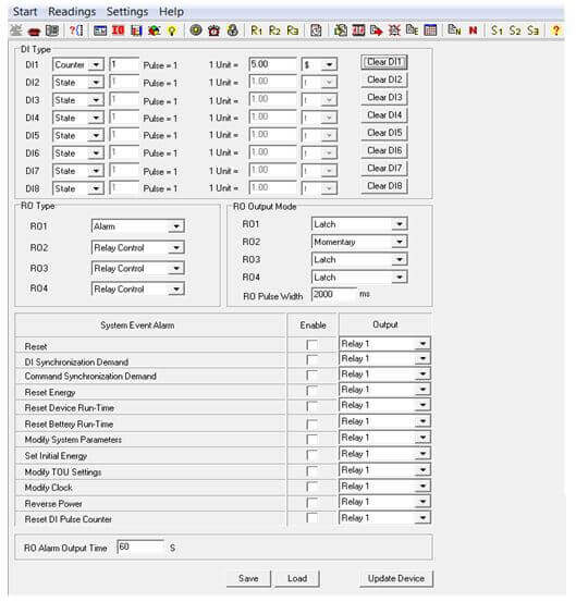
Figure 3: DI, RO and Event Settings
Configure Software Alarm Settings
- Click on "Settings" from the upper menu and then select "Alarm settings" to configure the meter to enabled alarms.
Setting up the alarm includes selecting an alarming parameter, a condition, delay time (ms) and an alarming output. Users can set up to a maximum of 10 alarms.
- Enable alarm by checking off the Box "Enable Alarm"
- Enable preferred alarm channel(s) by checking off the "Enable" box next to the channel.
- Under the "Alarm Channel" column select the parameter either from the Real-time metering or a Demand parameter and select a user for whom the alarm will be for from the drop down box.
- Choose the required "Setting" or condition for alarm i.e. greater than >, equal to = or less than <.
- Enter the setpoint, where the setpoint is expressed by a percentage of the rated value.
Note: The rated current is defined as ¼ of the full-scale current.
For Example: With the full scale current set as 60A, the rated current will be 15A. To have an alarm trigger when the current is greater than 15A, the setpoint must be set to 100%.
Example: Rated voltage is 220 V, and the CT has a rating of 5 A, an alarm is required for when a tenant's real power is larger than 3kW. Since the rated power is 220*5= 1.1 kW, then 3 kW is 273% of 1.1 kW and so the alarming setpoint would be set as 273.
- Type in the desired Delay (ms) before alarm is triggered.
- Select an output from the dropdown box to configure a RO channel to be triggered once an alarm event occurs or no output.
Make sure to click "Update Device" after making any changes in order to save the settings.
For convenience, you can also save and load these settings on to other AcuRev meters.
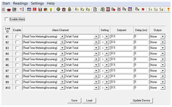
Figure 4: Alarm Settings
Configure Time-of-Use Settings
- Click on "Settings" from the upper menu and then select "TOU Settings".
The parameters to set are as followed:
- Season Setting: Can set up to a maximum of 14 seasons. Each season can have its own TOU Schedule.
- Schedule Setting: Can have a maximum of 8 schedules. Each schedule can be divided up into segments.
- Segment Setting: Can have up to a maximum of 14 segments. Each segment can have its own tariff.
- Tariff Setting: Can set up to a maximum of 4 tariffs.
- The four tariffs are sharp, peak, valley and normal and are represented by the numbers 1-4 respectively.
- If the Tariff setting parameter is set as 4 then all 4 tariffs will be available.
- If the parameter is set as 2 then only the first 2 tariffs (sharp and peak) will be available.
- Weekend Setting: Can set up the schedule number according to weekends. Assign the weekend a schedule.
- Holiday Setting: Can set up to a maximum of 30 holidays.
Note: If the public holiday and weekend schedule number is set as 0, it means these public holidays are unavailable. If the weekend and public holidays are overlapped, the public holiday overrides the weekend settings since the holiday has a higher priority.
- Click on "Enable TOU" to enable the TOU Function.
TOU Seasons:
Fill in the appropriate slots in the TOU Seasons based on the number in the "Season Settings". If the "Season Settings" is set as 2 then only the first 2 slots of the "TOU Seasons" must be filled in. Note: If the slot is filled inappropriately then the TOU function will be disabled- Enter the start date into the TOU season slot in the following format "MM-DD-ID"
- MM stands for month
- DD stands for date
- ID represents the TOU schedule (1-8)
The dates should be organized in chronological order (The earliest date comes first and the later date follows).
Note: Entering the dates in the wrong order will cause the TOU function to be disabledHolidays:
Fill in the appropriate slots under the "Holidays" setting based on the number in the "Holiday Setting". If the "Holiday Setting" is set as 3 then only the first 3 slots of the "Holidays" must be filled in otherwise the TOU function will be disabled.
- Enter the date of the Holiday in the Holiday schedule slot in the following format "MM-DD-ID"
- MM stands for month
- DD stands for date
- ID represents the TOU schedule (1-4)
The dates of the Holiday schedules do not need to be organized in chronological order.
TOU Schedules:
Each TOU schedule is represented by a 24 hour cycle. Fill in the appropriate slots in the TOU Schedule based on the number in the "Schedule Setting". If the "Schedule Setting" is set as 8 then all 8 of the "TOU Schedules" must be filled in.
The amount of slots to fill in each TOU Schedule depends on the "Segment Setting" parameter. If the "Segment Setting" parameter is set as 3 then the first 3 slots in each TOU Schedule must be set, otherwise the TOU function will be disabled.
- Enter the start time into the TOU Schedule slot in the following format "HH-MM-ID"
- HH stands for hour in 24 hour format
- MM stands for minutes
- ID represents the tariff to follow (1-8)
The time should be organized in chronological order (The earliest time comes first and the later time follows).
Note: Entering the time in the wrong order will cause the TOU function to be disabled
Daylight saving time (DST) can be enabled as one of two formats:
- Fixed date option: If you choose a fixed date option, you set the format according to a fixed date for the DST switch: in the format of month/ day/ hour/ minute/ adjust time (in minutes).
- Non-Fixed date option: If you choose the non-fixed option, DST will be implemented by which day of which week, with the format as month/ which day/ which week/ hour/ minute/ adjust time (in minutes).
Setting the DST will cause the meter to automatically switch to and from daylight saving time. When the clock starts to run on daylight saving time, the meter will automatically adjust its clock to a time period in advance, while the clock is running to the end of daylight saving the meter will adjust its clock back to a previous time period.
Make sure to click "Update Device" after making any changes in order to save the settings. If no errors are found then the TOU energy accumulation will begin.
For convenience, you can also save and load these settings on to other AcuRev meters.
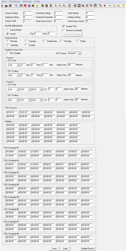
Figure 5: Time-of-Use Settings
Configure Ten Year Holiday Settings
- Click on "Settings" from the upper menu and then select "Ten Year Holiday Settings".
- Click on the "Enable Holiday Years Settings" box to configure the 10 year holiday period.
- The user must specify the "Start Year" and "Ending Year" for the 10 year (or less) period. I.e. 2014 – 2023.
- The holiday format is month/day; holiday code; holiday schedule. After the format setup, click on "Make Holiday Settings (10 year)", then a holiday table for the next decade will be generated.
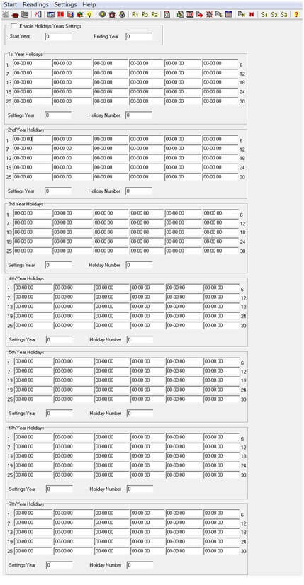
Figure 6: Ten Year Holiday Settings
Make sure to click "Update Device" after making any changes in order to save the settings.
For convenience, you can also save and load these settings on to other AcuRev meters.
Configure IP Address and Ethernet Settings
- Click on "Settings" from the upper menu and then select "Net Module Settings" to configure the Ethernet settings.
Make sure to select "Use the following IP settings"
- Enter the IP Address and Gateway
- Click "Restore to Defaults" to revert back to factory settings
Note: The DNS parameters must be set correctly to use the SMTP functions.
Make sure to click "Update Device" after making changes so that the changes can be saved on the meter.
Note: Clicking "Update Device" will prompt you to restart the NET module, click "Yes" so that the new settings will be saved.
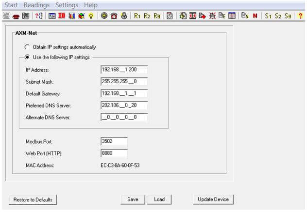
Figure 7: Net Module Settings
Configure Email Function
- Click on "Settings" from the upper menu and then select "Net Module 2 Settings" to configure the settings for the email function.
The "Mail From" section can be set as followed:
- Enter a name or phrase which will appear in the email to let you know who this mail is from i.e. "Tech Support".
You can enter up to 3 recipients for the emails:
- Enter the email addresses of the recipients you wish to have the email sent to in "Mail To #1", "Mail To #2" and "Mail To#3".
The "Mail Subject" can be set as followed:
- Enter a subject which will appear every time the email is sent i.e. "Test Mail".
"Mail Interval Sending" is how frequently the recipients will receive an email:
- Enter a value between 5 minutes to 1440 minutes i.e. entering 5 minutes in the Mail interval sending will enable emails to be sent every 5 minutes.
Note: Entering a value of 0 will disable the Mail Interval Sending
Mail Server is the name of a valid SMTP server where the mail will be sent from:
- Enter the SMTP server in here i.e. mail.accuenergy.com
Note: Servers such as "Gmail", "Yahoo" and "Hotmail" cannot be used as the Mail Server.
- Enter the "SMTP User Name" and "SMTP User Password" for the SMTP Server set above.
Select the content of the email in the "Select Mail Contents for time interval type"
- Check off the box for the parameters you wish to receive mail on.
- Checking off "Alarm Event", "SOE Event" or "System Event" will cause an email to be sent every time a new event occurs.
Make sure to click "Update Device" after making changes so that the changes can be saved on the meter.
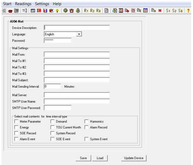
Figure 8: Net Module 2 Settings
Configure Data Log for AcuRev 2000
- Click on "Settings" from the upper menu and then select either "Data Log 1", "Data Log 2" or "Data Log 3" to configure up to three data logs.
The different Data Log options (Data Log 1, Data Log 2 and Data Log 3) are available in case you need to set different parameters with different settings such as different logging interval.
- Select from the different groups of parameters from the drop down menu, and then add the required parameters to the box on the right of the data log page.
- Drag the "Sectors" bar to the required length. Having the bar at a maximum of 100 means the data log will use all of the meter's memory.
- The total sector number between Data Log 1, Data Log 2 and Data Log 3 must not be more than 100.For example:
- If you are using just Data Log 1, you can have the sector all the way to 100
- If you are using Data Log 1 and Data Log 2, you can have both sectors at 50
- If you are using Data Log 1, Data Log 2 and Data Log 3, you can have the sectors at 30, 30 and 40.
In the "Other" Section:
- Select the Logging Interval this can be set from 1 minute to 1440 minutes (one day)
In the "Logging Mode" Section:
- Select "Continuous" to start logging data immediately and continuously. There is an option to set a start time to log data:
- Check the "Start at" box and put in the "Hour" and "Min" to start data logging at that specific time.
Note: When the memory is full, a sector is deleted and the data logging will continue.
- Select "Interval" to start and end data logging at a set time
- Select the Date and time you will like to start data logging
- Select the Date and time you will like to end data logging
Note: When the memory is full, the data logging will stop.
Make sure to click "Update Device" after making changes so that the changes can be saved on the meter.
Note: When you click on "Update Device", the meter's data log memory will be erased.
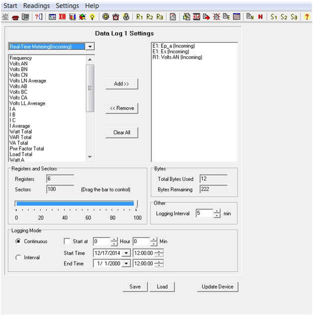
Figure 9: Data Log Settings
