Product Support
Configure AcuView Software for use with AcuDC 240
Configure AcuView Settings
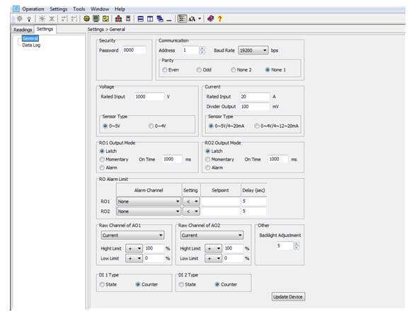
- From the left navigation panel click on the "Settings" tab and then on "General". You can set up the system parameters and I/O settings from this section.
- Click on ‘Update Device’ after making changes, so that the changes can be saved on the meter.
Security & Communication: You can set the meter’s password, device address, Baud Rate and parity from this section.
Voltage & Current: If you are measuring your voltage using a voltage Hall Effect sensor and/or your current using either a Hall Effect sensor or a shunt, you will have to set the Voltage and/or Current sections.
RO1 Output Mode/RO2 Output Mode: This is available with the ‘X3’ module.
Choose between three models:
- Latch: To manually turn on and off the relay
- Momentary: To turn on the relay for a set number of seconds before it goes back off.
- If momentary mode is selected, set the delay time ‘On Time’; the range is 300-5000ms. The delay time has an error of up to 3ms (due to the relay action time error).
- Alarm: To trigger the relay output through an alarm event.
RO Alarm Limit: Set the Alarm Channel, Setting, Setpoint and Delay (in sec) for both RO1 and RO2; this is needed if RO1/RO2 Output mode is set as ‘Alarm’
Raw Channel of AO1/Raw Channel of AO2:This is available with X1 and X2 modules.
Select the parameter (Voltage, Current, Power) you will like to send as an Analog Output.
Set the High and Low Limit based on the parameter you have selected.
Note:
- When AO parameter is set as voltage, the upper and lower limit setting range is between 0% - 100%. E.g. it can be set as: 0% - 100%, 0% - 50% etc.
- When AO parameter is set as current or power, there are four different modes for the upper and lower limit setting range. It can be between: 0% - +100%, 0% - -100%, -100% - +100%, and 0% - ±100%. E.g. it can be set as: 0% - +50%, 0% - -50% etc.
- Upper Limit cannot be 0%
Other:
- You can adjust the backlight brightness under the Backlight Adjustment section. The range is from 1 to 5.
DI 1 Type/ DI 2 Type:Select DI 1 or DI 2 as:
- State: DI will act as a switch status monitor
- Counter: DI will act as a pulse counter

Figure 20: General Settings
Configure Data Log using the Meter's Onboard Memory
You can set up the meter to log data on the onboard memory.
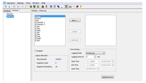
- From the left navigation panel click on the settings tab then click "Data Log" to access the data log setting page.
Parameter Selection: Select the parameters you would like to log (from the left box), click "Add" to add them to the box on the right.
Enable Data Log: Make sure you check the box ‘Enabled’ to enable data log.
Time Setting: There are three different Logging Modes.
- Continuous: This will start logging data immediately, after the "Update Device" button is clicked.
- In this mode, you will have to set the Logging Interval.
- Scheduling: This will start logging data from a set Start Time.
- In this mode, you will have to set the Logging Interval and Start Time.
Note: When the memory is full, a memory sector is deleted and the data logging will continue for the above two modes.
- Interval: This will log data from a start time to an end time.
- In this mode, you will have to set the Logging Interval, as well as the Start Time and End Time.
Note: When the memory is full, the data logging will stop.
Make sure to click on ‘Update Device’ after making changes, so that the changes can be saved on the meter.
Note: When you click on ‘Update Device’, the meter’s data log memory will be erased.

Figure 21: Data Log Readings
Configure the Data Log to log Readings on the Computer's Memory
This applies to AcuDC 240 series meters with communication option; the meters do not need to have onboard memory since the data will be logged directly on the computer’s memory.
You can set up the meter to log data directly on the computer memory. You must always be connected to the software for this data log method to work.
You can access this data log setting by clicking on the ‘Settings’ option located on the menu toolbar, and then clicking on ‘Data Log Settings’.

Figure 22: Accessing Data Log
The Data Log Setting window will open. This is shown below:

Figure 23: Data Log Settings
Make sure you check the ‘Enabled’ box in the window.
Under the ‘Logging Items of Selection’ Section: click on the required groups of parameters you will like to log.
Under the ‘Logging Options’ Section:
- Choose the "Logging Data Interval".
- Choose between the options "Log data until file is full" or "Specify Log file duration"
- If "Specify Log file duration" is selected: Choose how often you want a new file created.
- Choose the "Log file format" you want the file(s) saved as.
Choose the "Log file folder location" where the file(s) will be saved.
Once everything is set, click "OK".
Finally, make sure you click the icon:![]() on the top of the screen to start data logging on the computer.
on the top of the screen to start data logging on the computer.
You can click the icon:![]() on the top of the screen to stop data logging.
on the top of the screen to stop data logging.
WARNING:
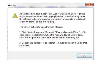
If Excel is chosen as the Log file format, After you click on the icon: ![]() to start data logging, a warning window will pop up. Take note of the warning in order to prevent your files from being corrupt.
to start data logging, a warning window will pop up. Take note of the warning in order to prevent your files from being corrupt.

Figure 24: Warning Message
